Electronic apparatus
A technology for electronic equipment and display panels, applied in the direction of equipment, electrographics, electrical components, etc.
- Summary
- Abstract
- Description
- Claims
- Application Information
AI Technical Summary
Problems solved by technology
Method used
Image

Examples
no. 1 approach
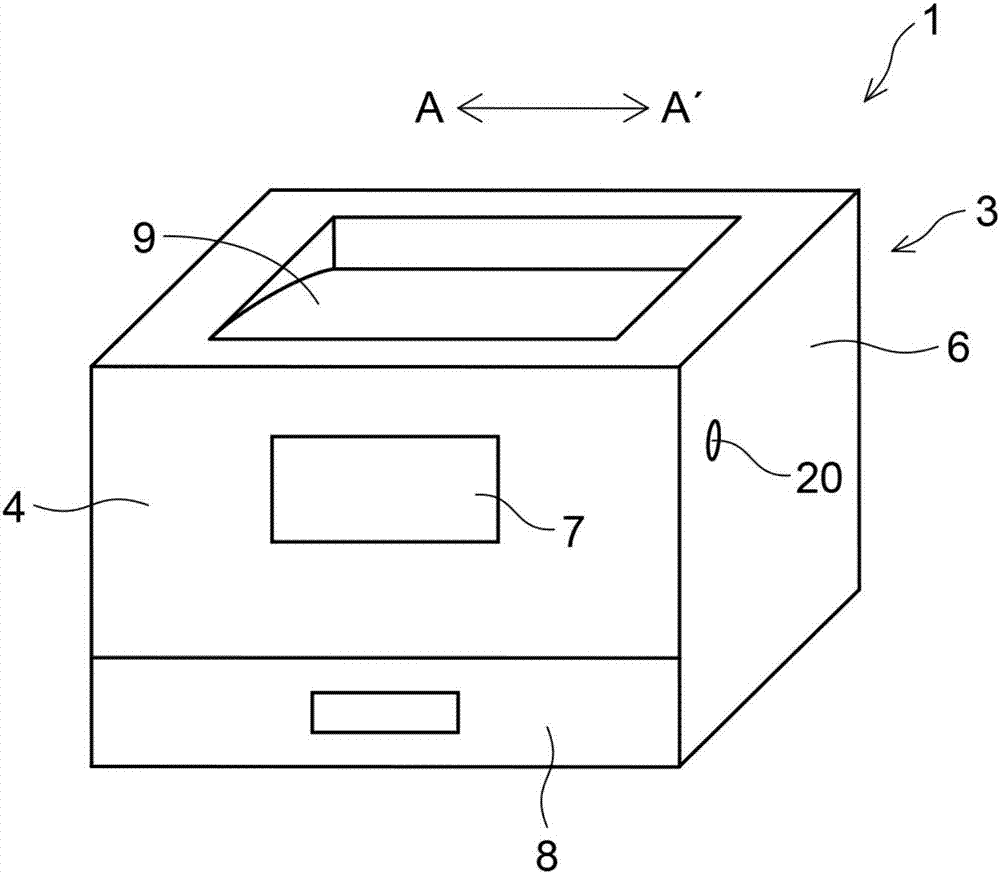
[0021] refer to Figure 1 ~ Figure 4 An image forming apparatus (electronic device) 1 according to a first embodiment of the present invention will be described. Such as figure 1 As shown, the image forming apparatus 1 includes an apparatus main body 3 having a substantially hexahedral structure. The device main body 3 has a first side 4 as a front side of the device, and a second side 5 disposed adjacent to the first side 4 and sandwiching the first side 4 (see figure 2 ) and the third side 6, and the four sides formed by the back of the device. A display panel 7 is provided on the first side 4, and the display panel 7 is composed of a liquid crystal panel that displays information related to image forming operations, button images for touch panel operations, and the like. In addition, a paper feeding cassette 8 is provided at a lower portion of the first side surface 4 , and the paper feeding cassette 8 can be attached to and detached from the apparatus main body 3 in th...
no. 2 approach
[0046] Such as Figure 8 As shown, in the second embodiment of the present invention, a lever portion 10c is provided on the holding member 10 that holds the display panel 7 so as to be rotatable in the horizontal direction about the rotation axis O as the center, and the lever portion 10c is directed to the display panel 7. The opposite side (device back side) of the panel 7 protrudes.
[0047] The operating mechanism 20 is constituted by an operation unit 21 extending in the direction of the arrow AA′ of the device main body 3 . A link mechanism 40 is attached to the central portion of the operation portion 21 in the longitudinal direction, and the link mechanism 40 connects the operating mechanism 20 and the holding member 10 . The link mechanism 40 has a pair of gripping portions 41 that grip the rod portion 10 c in a rotatable manner, and moves in the arrow AA′ direction together with the action mechanism 20 . In the present embodiment, the clamping portion 41 is config...
no. 3 approach
[0054] In the third embodiment of the present invention, as Figure 11 As shown, the holding member 10 that holds the display panel 7 rotatably in the horizontal direction is provided with a plate-shaped portion 10d protruding to the side opposite to the display panel 7 (device rear side). An engaging recessed portion 10e is formed on the plate-like portion 10d away from the display panel 7 from the center toward the outside in the arrow AA′ direction.
[0055] The operating mechanism 20 is composed of an operation portion 21 and a protruding portion 22 . In the present embodiment, the protruding portion 22 protrudes downward from the center portion in the longitudinal direction of the operation portion 21 and is inserted and engaged with the engaging recessed portion 10 e of the holding member 10 .
[0056] When the user pushes (operates) the operating mechanism 20 from the second side surface 5 side (arrow A direction) to move the operating mechanism 20 in the arrow A' dire...
PUM
 Abstract
Description
Claims
Application Information
 - R&D
- Intellectual Property
- Life Sciences
- Materials
- Tech Scout
- Unparalleled Data Quality
- Higher Quality Content
- 60% Fewer Hallucinations
Browse by: Latest US Patents, China's latest patents, Technical Efficacy Thesaurus, Application Domain, Technology Topic, Popular Technical Reports.
© 2025 PatSnap. All rights reserved.Legal|Privacy policy|Modern Slavery Act Transparency Statement|Sitemap|About US| Contact US: help@patsnap.com