Head clamping spray cooling device

A spray cooling and clamping technology, applied in metal rolling, metal processing equipment, mandrels, etc., can solve the problems affecting the production rhythm and production efficiency of seamless steel pipe production lines, ineffective production operation time, and waste of production time. Achieve the effect of reducing the degree of manual intervention, saving production time and reducing labor intensity

CN107282637BActive Publication Date: 2019-04-05TAIYUAN HEAVY MACHINERY GRP ENG TECH R & D CO LTD
7 Cites 0 Cited by

Patent Information

Authority / Receiving Office
CN · China
Patent Type
Patents(China)
Current Assignee / Owner
Publication Date
2019-04-05

Smart Images

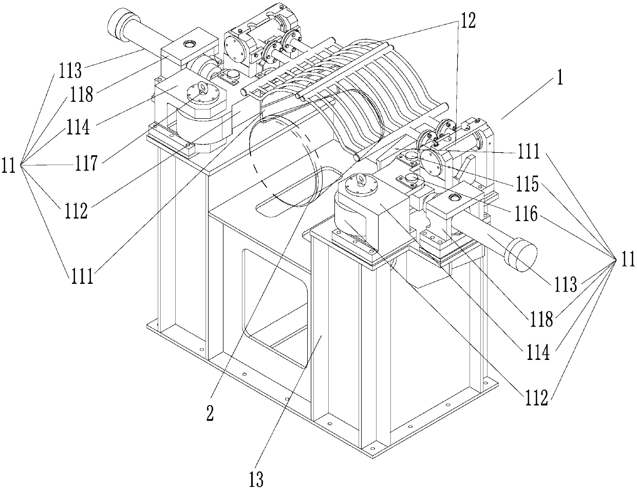
  • Figure 1
    Figure 1
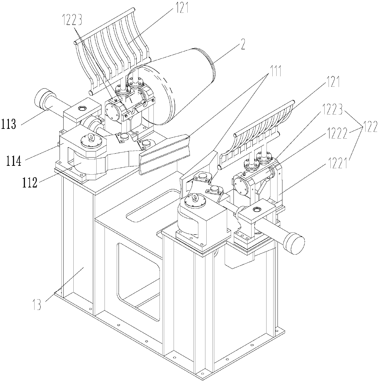
  • Figure 2
    Figure 2
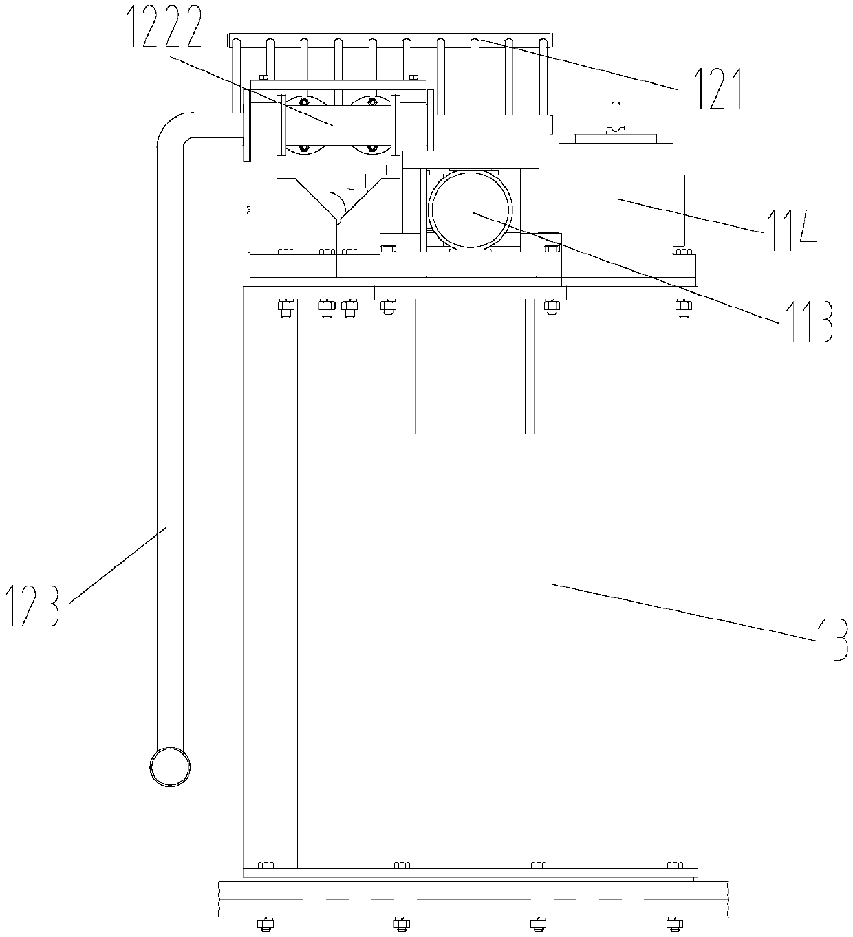
  • Figure 3
    Figure 3
Patent Text Reader

Abstract

The invention provides a top clamping spraying cooling device. The device comprises a clamping assembly and a spraying cooling assembly. The clamping assembly comprises paired clamping mechanisms which are symmetrically arranged about the axis of a clamped top. Each clamping assembly comprises a clamping claw, a rotating arm with the first end hinged to the clamping claw and a driving part with the telescopic movement end hinged to the second end of the rotating arm. Each clamping mechanism further comprises a rotating arm seat, wherein the third end of the rotating arm is hinged to the rotating arm seat. The paired clamping claws are converted between the clamping state that the top is clamped and the releasing state that clamping of the top is released under the drive of the respective rotating arms under the telescopic effect of the driving ends of the respective driving parts. By means of the top clamping spraying cooling device, three processes of top disengaging, top clamping and spraying cooling can be synchronously conducted at the same station and are seamlessly connected with the previous and posterior production work processes, and waste of invalid action time is avoided; and the production time of steel pipes is saved, and the production efficiency is improved.
Need to check novelty before this filing date? Find Prior Art

Description

technical field

[0001] The invention relates to steel rolling technology, in particular to a plug clamping spray cooling device. Background technique

[0002] In the piercing and rolling or rotary expansion process of the seamless steel pipe production line, there is a production process: after the piercing and rolling of the ejector rod with the plug is completed, the plug leaves the piercing and rolling host with the ejector rod. At this time, the ejector rod and the plug need to be temporarily separated. The plug stays at one station, and the ejector rod enters the next station with the pierced and rolled capillary. At this time, the plug is moved into the cooling system, and the cooling process of the plug is carried out. Return the ejector pin that has been separated from the capillary to the combined station with the plug. Because the clamping release and cooling of the plug are two stations and two processes, it takes time to move. At the same time, before the top o...

Examples

Embodiment Construction

[0025] In order to make the object, technical solution and advantages of the present invention clearer, the technical solution of the present invention will be clearly and completely described below in conjunction with the embodiments of the present invention and corresponding drawings. Apparently, the described embodiments are only some of the embodiments of the present invention, but not all of them. Based on the embodiments of the present invention, all other embodiments obtained by persons of ordinary skill in the art without making creative efforts belong to the protection scope of the present invention.

[0026] The terms "first", "second", etc., if present, in the description and claims and the above drawings are used to distinguish similar parts and not necessarily to describe a specific order or sequence. It is to be understood that the data so used are interchangeable under appropriate circumstances such that the embodiments of the application described herein can be...