Micro-polluted water source biological treatment device

A biological treatment and water source water technology, applied in the direction of biological water/sewage treatment, water/sludge/sewage treatment, chemical instruments and methods, etc., can solve the problems of ineffective removal of turbidity and CODMn, increased power and backwashing costs, It is unfavorable for problems such as denitrification and denitrification, and achieves the effects of reducing system aeration and backwashing energy consumption, convenient management, and protecting backwashing pipes and pores

Active Publication Date: 2018-01-12
ZHEJIANG OCEAN UNIV
View PDF3 Cites 2 Cited by
  • Summary
  • Abstract
  • Description
  • Claims
  • Application Information

AI Technical Summary

Problems solved by technology

However, the aerobic biological aeration tank has a single structure and needs to be operated under high aeration conditions to maintain the suspension of the filler, which increases the cost of aeration and the high aeration conditions make the dissolved oxygen concentration in the water often close to saturation, which is not conducive to denitrification and denitrification , and cannot effectively remove turbidity and CODMn in source water
The biofilm formation time of the biofilter carrier can be as long as several months, the start-up is relatively slow and the water flow resistance is large and easy to cause blockage, which increases the cost of power and backwashing
In addition, in the process of biological treatment of source water, the process application is relatively single, limited by the oligotrophic water quality of slightly polluted source water, the growth of microorganisms in the biological treatment process is extremely slow, and it takes a long start-up time to obtain ideal treatment performance

Method used


Image

  • Micro-polluted water source biological treatment device
  • Micro-polluted water source biological treatment device
  • Micro-polluted water source biological treatment device

Examples


Embodiment 1

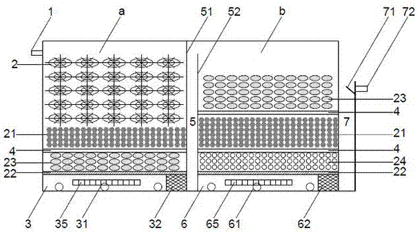
[0022] Such as figure 1Shown, a kind of slightly polluted water source water biological treatment device, it comprises reactor body, and reactor body comprises pre-treatment unit a and after-treatment unit b, and pre-treatment unit a and after-treatment unit b are formed by lower baffle wall 51 and The flow channel 5 surrounded by the upper baffle wall 52 is separated, and the bottom of the pretreatment unit a is provided with a first bottom outlet chamber 3, which includes a first mud discharge pipe 31, an aeration pipe 35, a first The load-bearing porous brick 32, the bottom of the post-processing unit b is provided with a second bottom water outlet chamber 6, the second bottom water outlet chamber 6 includes a second mud discharge pipe 61, an aeration pipe 65, and a second load-bearing porous brick 62, and the upper left of the pre-treatment unit a There is a water inlet pipe 1 at the top of the pretreatment unit a, and there are suspended packing layer 2, modified zeolite ...

Embodiment 2

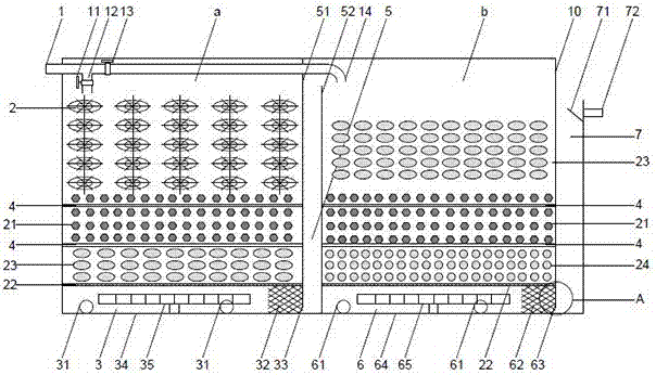
[0025] Such as Figure 1-5 Shown, a kind of slightly polluted water source water biological treatment device comprises a reactor body, and the reactor body comprises a pre-treatment unit a and a post-treatment unit b, and the pre-treatment unit a and the post-treatment unit b are composed of a lower baffle wall 51 and an upper The flow channel 5 surrounded by the baffle wall 52 is separated; the upper left side of the front processing unit a is provided with a water inlet pipe 1, the first water inlet pipe 12 is arranged at the upper left inside of the pre-processing unit a, and the upper left inside of the post-processing unit b A second water inlet pipe 14 is provided, the first water inlet pipe 12 and the second water inlet pipe 14 are connected to the water inlet pipe 1, and the first water inlet pipe 12 and the second water inlet pipe 14 are respectively provided with a first valve 11 and a second valve 13; The inside of the pre-processing unit a is provided with a suspen...

Embodiment 3

[0033] Such as Figure 1-5 As shown, a biological treatment device for slightly polluted source water, when the device is normally treating slightly polluted water, the reactor is constructed with plexiglass, steel or reinforced concrete. Open the first valve 11, close the second valve 13, the slightly polluted source water enters the pretreatment unit a from the side of the reactor body through the water inlet pipe 1 and the first water inlet pipe 12, and passes through the suspension packing layer 2, the modified zeolite layer 21, The cobblestone layer 23 and the permeable support plate 22 enter the first bottom water outlet chamber 3, and the water flow enters the flow channel 5 along the first load-bearing porous brick 32 and the gap between the bricks, and then flows into the post-processing unit b through the upper baffle wall 52, and passes through For the treatment of the cobblestone layer 23, modified zeolite layer 21, and quartz sand layer 24 in the post-processing u...


PUM

PropertyMeasurementUnit
diameteraaaaaaaaaa
pore sizeaaaaaaaaaa
diameteraaaaaaaaaa

Abstract

The invention provides a micro-polluted water source biological treatment device, which belongs to the field of sewage treatment and comprises a reactor body, wherein the reactor body comprises a pre-treatment unit and a post-treatment unit, the pre-treatment unit is internally provided with a suspension filler layer, a modified zeolite layer, a cobble layer and a water-permeable supporting plate;the post-treatment unit is internally provided with a cobble layer, a modified zeolite layer, a quartz sand layer and a water-permeable supporting plate; the bottoms of the pre-treatment unit and thepost-treatment unit are both provided with a bottom water outlet chamber; a downflow weir and a water outlet pipe are arranged at the right side of the post-treatment unit and a backwash pipe is alsoarranged inside the reactor. The device has the advantages of capability of effectively improving the diversity of microbial living environment, strengthening the attachment of microorganisms and increasing the diversity of system biological species so as to strengthen the removal of nitrogen and organic matters in a micro-polluted water source, capability of effectively reducing system blockage,reducing system aeration and backwash energy consumption, easy management and the like, and can greatly reduce system operating cost.

Description

technical field [0001] The invention relates to the field of sewage treatment devices, in particular to a slightly polluted water source water biological treatment device. Background technique [0002] In recent years, the discharge of industrial, agricultural and domestic sewage has increased the level of organic matter and nitrogen in natural water bodies year by year, seriously threatening the development and utilization of water resources. The pollution of source water seriously threatens the health of people, and the situation of drinking water safety is becoming increasingly severe, which has attracted widespread attention at home and abroad. At present, the treatment methods of polluted source water mainly include physical, chemical and biological treatment methods. Among them, physical methods such as filtration and sedimentation process are mainly used to treat turbidity and heavy metal pollution in source water, and cannot effectively remove nitrogen and organic m...

Claims


Application Information

Patent Timeline
Patent Type & Authority Applications(China)
IPC IPC(8): C02F3/34
Inventor 阳广凤冯丽娟穆军孙静亚
Owner ZHEJIANG OCEAN UNIV
Why Eureka
Try Eureka