The installation structure of the telescopic arm
A technology for installing structures and telescopic arms, which can be used in cranes and other directions to solve problems such as inability to use rotating pillars
- Summary
- Abstract
- Description
- Claims
- Application Information
AI Technical Summary
Problems solved by technology
Method used
Image

Examples
no. 1 Embodiment
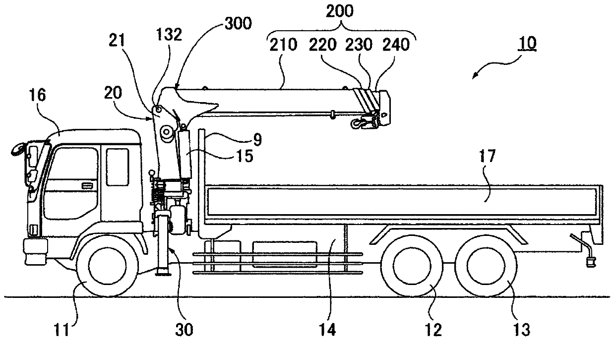
[0024] figure 1 A truck crane (crane) 10 is shown as a working machine to which a telescopic boom mounting structure is applied.
[0025] The truck crane 10 has a main frame 14, a rotating strut 20, a telescopic arm 200, a pitching cylinder 15, a pair of outrigger devices 30 (only one is shown), a cab 16, a loading platform 17, etc., wherein the main frame 14 is Extending in the front-rear direction, the front wheel 11 and the first and second rear wheels 12, 13 are provided; the rotating strut 20 is provided on the main frame 14 in a rotatable manner; The upper part of the pillar 20; the pitching cylinder 15 makes the telescopic arm 200 pitch; a pair of outrigger devices 30 are arranged on both sides of the main frame 14 near the position of the rotating pillar (position relative to the front-rear direction); the cab 16 is in the The main frame 14 is arranged on the front side of the rotating pillar 20 ; the loading platform 17 is arranged on the rear side of the rotating pi...
no. 2 Embodiment
[0049] Figure 4 The attachment structure of the telescopic arm of the second embodiment is shown. Figure 4 The illustrated bracket 400 is set such that a predetermined area (third predetermined area) 401 is an area spanning from the base piece 312 to the protruding piece 313, wherein the predetermined area (third predetermined area) 401 includes the axis of the base piece 312. part 314 and the shaft part 316 of the protruding piece 313. The width between the predetermined regions 401 and 401 is set to W1 as in the first embodiment, and the width of other parts is set to W2, and W2 is set to be larger than W1. Moreover, the front edge part 401K which is the boundary of each predetermined area|region 401 inclines in the same direction as 1st Example, ie, from the rear side to the front side toward the front end side of a telescopic arm.
[0050] According to the attachment structure of the telescopic arm of the second embodiment, an existing shaft member can be used as the s...
no. 3 Embodiment
[0053] Figure 5 The installation structure of the telescopic arm of 3rd Example is shown. Figure 5 In the shown bracket 500 , a predetermined region (first predetermined region) 315 similar to the first embodiment and a predetermined region (second predetermined region) 501 including the shaft portion 316 in the protruding piece 313 are set. The width between the predetermined regions 501, 501 is set narrower than the width of the base arm 210, and the width between the predetermined regions 501, 501 does not have to be W1. The other configurations are the same as those of the first embodiment, and thus descriptions thereof are omitted.
[0054] According to this bracket 500, the same effect as that of the second embodiment can be obtained.
PUM
 Abstract
Description
Claims
Application Information
 - R&D
- Intellectual Property
- Life Sciences
- Materials
- Tech Scout
- Unparalleled Data Quality
- Higher Quality Content
- 60% Fewer Hallucinations
Browse by: Latest US Patents, China's latest patents, Technical Efficacy Thesaurus, Application Domain, Technology Topic, Popular Technical Reports.
© 2025 PatSnap. All rights reserved.Legal|Privacy policy|Modern Slavery Act Transparency Statement|Sitemap|About US| Contact US: help@patsnap.com