Method for mapping between PPI display pixels and echo information

A technology for displaying pixels and display methods, applied in radio wave measurement systems, instruments, etc., can solve the problems of no-echo mapping of pixels, occupying CPU resources, slow data processing speed, etc. The effect of implementation

Active Publication Date: 2018-03-23
WUHAN BINHU ELECTRONICS
View PDF3 Cites 7 Cited by
  • Summary
  • Abstract
  • Description
  • Claims
  • Application Information

AI Technical Summary

Problems solved by technology

[0003] In the traditional method, when establishing the mapping relationship between echo information and PPI display pixels, each distance unit in each azimuth is mapped to the corresponding pixel point in the PPI display, and it is easy for multiple distance units to be mapped to a pixel PPI display point at the same time. , and each data echo information point is mapped, the data processing volume is large, and the system data processing time is long. As the current echo information volume is increasing, the slow data processing speed will easily cause the system to run stuck or even often crash. Case
[0004] For example, with the development of technology, the distance resolution and azimuth resolution of the radar echo signal are gradually improving, and the amount of original echo data that the radar can receive also increases. A large number of coordinate conversions are required when updating the PPI display Operation realizes the mapping between echo data and pixels, which takes up a lot of CPU resources and affects processing efficiency
[0005] On the other hand, the functions required for PPI display are becoming more and more abundant. Not only can the display range be adjusted, but it also has various display methods such as hollow, eccentric, and delay. If only the echo data is mapped to the pixels in the display, it is possible There is a problem that some pixels do not have corresponding echo mapping relationship, resulting in missing display content
Moreover, in the process of changing the display range or switching the display mode, it is necessary to re-establish the mapping relationship, which consumes a lot of time and resources.

Method used


Image

  • Method for mapping between PPI display pixels and echo information
  • Method for mapping between PPI display pixels and echo information
  • Method for mapping between PPI display pixels and echo information

Examples


Embodiment Construction

[0024] Glossary:

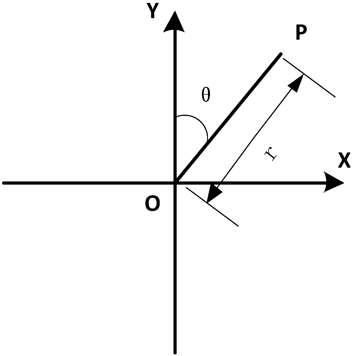
[0025] The polar coordinate system refers to the coordinate system composed of poles, polar axes and polar diameters in a plane. Such as figure 2 As shown, take a certain point O on the plane, which is called a pole. A ray OY is drawn from O, which is called the polar axis, and then a unit length is taken, and the anticlockwise direction of the specified angle is usually positive. In this way, the position of any point P on the plane can be determined by the length r of the line segment OP and the angle θ from OX to OP, denoted as P(r, θ); r is called the polar radius of point P, and θ is called point P polar angle.

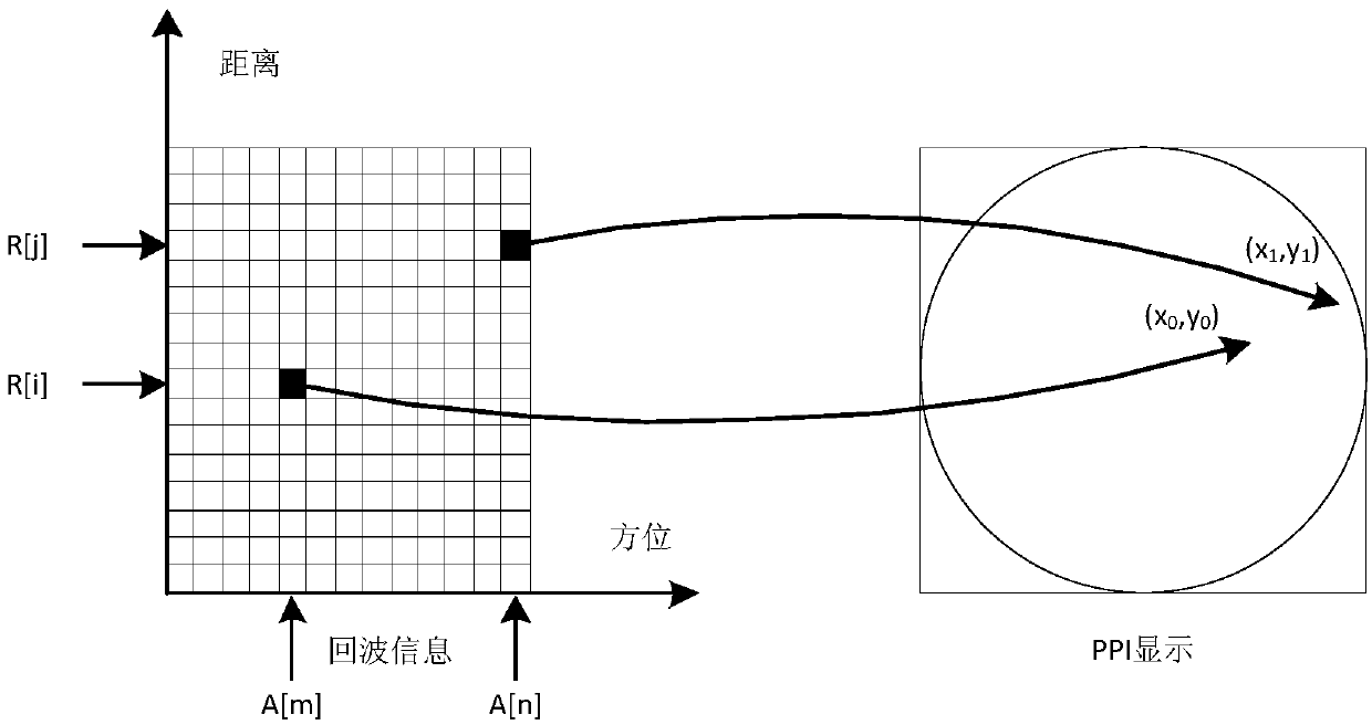
[0026] In the present invention, the echo information must include a distance unit and an azimuth unit, and the azimuth unit is the polar angle resolution of the echo information in the polar coordinate system, and the distance unit is the smallest distinguishable distance of the echo information in each azimuth unit. unit.

[0027] In or...


PUM


Abstract

The invention belongs to the field of terminal display, and particularly relates to a method for the mapping between PPI display pixels and echo information. The method of the invention simplifies a mapping relationship between echo data and screen pixels, obtains a mapping relationship between display pixel points and the azimuth and a relationship between the display pixel points and the distance respectively according to a PPI display mode and a display range, and ensures that each display pixel point has a corresponding distance unit. The method of the invention is clear and logical, has asmall calculation amount and an obvious effect, simplifies the redundant calculation steps, and is beneficial to implementation in engineering.

Description

technical field [0001] The invention belongs to the field of terminal display, in particular to a method for PPI display pixel mapping echo information. Background technique [0002] The Plan Position Indicator (PPI) outputs and displays the echo information in the form of Cartesian coordinates, but based on the electrical pulse scanning method, the echo information changes in the form of polar coordinates. When the PPI display updates the display, it needs to display and output the PPI display screen according to the mapping relationship between the echo signal and the PPI display pixel. [0003] In the traditional method, when establishing the mapping relationship between echo information and PPI display pixels, each distance unit in each azimuth is mapped to the corresponding pixel point in the PPI display, and it is easy for multiple distance units to be mapped to a pixel PPI display point at the same time. , and each data echo information point is mapped, the data proc...

Claims


Application Information

Patent Timeline
Patent Type & Authority Applications(China)
IPC IPC(8): G01S7/04
Inventor 陈斯林游
Owner WUHAN BINHU ELECTRONICS
Why Eureka
Try Eureka