Control method, device and equipment for monitoring equipment

A technology of monitoring equipment and control methods, applied to parts of color TVs, parts of TV systems, TVs, etc., can solve the problems of time-consuming errors, limited construction, large errors, etc., to reduce time-consuming and errors, Simple method, high precision effect

Pending Publication Date: 2022-04-12
三亚海兰寰宇海洋信息科技有限公司
View PDF0 Cites 0 Cited by
  • Summary
  • Abstract
  • Description
  • Claims
  • Application Information

AI Technical Summary

Problems solved by technology

In this method, few reference points will lead to large error and poor effect. If there are many reference points, there will still be large errors and it will take time to calibrate. When the image has no obvious feature points, the calibration process will be more difficult.
Part of the technology adopts the method of restricting the installation position of the gun camera and the dome camera so that the images of the two are approximately consistent, resulting in limited construction and considerable errors.

Method used


Image

  • Control method, device and equipment for monitoring equipment
  • Control method, device and equipment for monitoring equipment
  • Control method, device and equipment for monitoring equipment

Examples


Embodiment Construction

[0040]Exemplary embodiments of the present invention will be described in more detail below with reference to the accompanying drawings. Although exemplary embodiments of the present invention are shown in the drawings, it should be understood that the invention may be embodied in various forms and should not be limited to the embodiments set forth herein. Rather, these embodiments are provided for more thorough understanding of the present invention and to fully convey the scope of the present invention to those skilled in the art.

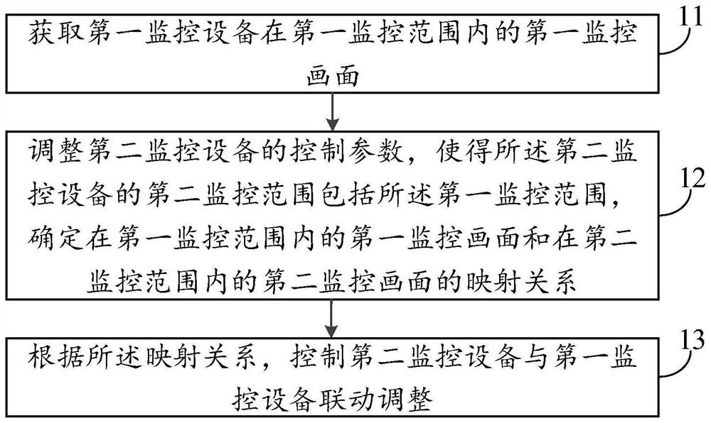
[0041] Such as figure 1 As shown, the present invention provides a control method for monitoring equipment, including:

[0042] Step 11, acquiring a first monitoring picture within the monitoring range of the first monitoring device;

[0043] Step 12, adjust the control parameters of the second monitoring device so that the second monitoring range of the second monitoring device includes the first monitoring range, determine the first monitorin...


PUM


Abstract

The embodiment of the invention provides a control method, device and equipment for monitoring equipment. The method comprises the following steps: acquiring a first monitoring picture of first monitoring equipment in a first monitoring range; adjusting a control parameter of second monitoring equipment to enable a second monitoring range of the second monitoring equipment to comprise the first monitoring range, and determining a mapping relation between a first monitoring picture in the first monitoring range and a second monitoring picture in the second monitoring range; according to the mapping relation, the second monitoring device and the first monitoring device are controlled to be adjusted in a linkage mode. According to the embodiment of the invention, time consumption and errors during manual picture calibration of the monitoring equipment are reduced.

Description

technical field [0001] The present invention relates to the technical field of equipment control, in particular to a control method, device and equipment for monitoring equipment. Background technique [0002] With the development of artificial intelligence technology, intelligent monitoring and capture technology has attracted more and more attention, such as the bayonet monitoring system, combined with deep learning technology to monitor ports, waterways, bayonets and other traffic arteries, the system usually uses guns and balls The machine linkage system, the gun machine detects and tracks the target, and the dome machine captures the shot. The accuracy of the gun-ball linkage of this system is particularly important. The linkage accuracy directly affects the real-time tracking of the target and the capture effect. [0003] The prior art usually adopts the calibration reference point of the bolt and the dome, and performs multi-point calibration through the pixels of the...

Claims


Application Information

Patent Timeline
Patent Type & Authority Applications(China)
IPC IPC(8): H04N7/18H04N5/232H04N5/247
Inventor 杨玉玉翟涛
Owner 三亚海兰寰宇海洋信息科技有限公司
Why Eureka
Try Eureka