Device and method for detecting three-window common-path interference based on beam splitter prism

A technology of interference detection and spectroscopic prism, which is applied in the field of interference detection, can solve the problems of low measurement accuracy of the interference detection method, and achieve the effect of being suitable for real-time dynamic measurement, compact structure, and ensuring anti-interference ability

Inactive Publication Date: 2014-12-03
HARBIN ENG UNIV
View PDF3 Cites 0 Cited by
  • Summary
  • Abstract
  • Description
  • Claims
  • Application Information

AI Technical Summary

Problems solved by technology

[0006] The present invention aims to solve the problem of low measurement accuracy of the existing interference detection method, and provides a three-window common optical path interference detection device and detection method based on a dichroic prism

Method used


Image

  • Device and method for detecting three-window common-path interference based on beam splitter prism
  • Device and method for detecting three-window common-path interference based on beam splitter prism
  • Device and method for detecting three-window common-path interference based on beam splitter prism

Examples


specific Embodiment approach 1

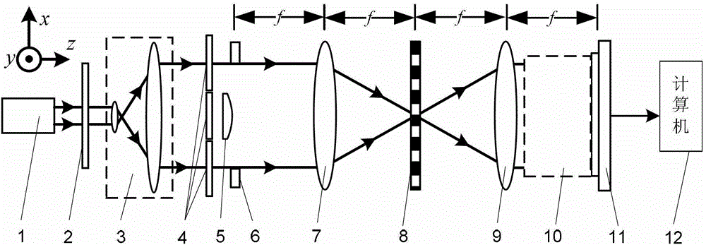
[0037] Specific implementation mode one: the following combination figure 1Describe this embodiment, the three-window co-optical path interference detection device based on the dichroic prism described in this embodiment, it includes a light source 1, it also includes a polarizer 2, a collimating beam expander system 3, three λ / 4 wave plates 4, The object to be measured 5, the rectangular window 6, the first lens 7, the one-dimensional periodic grating 8, the second lens 9, the light splitting synchronous phase shift system 10, the image sensor 11 and the computer 12, wherein λ is the light wavelength of the light beam emitted by the light source 1,

[0038] The light beam emitted by the light source 1 is incident on the light receiving surface of the collimated beam expander system 3 through the polarizer 2, and the outgoing beam after collimated and expanded by the collimated beam expander system 3 passes through three λ / 4 wave plates 4, to be tested The object 5 and the rec...

specific Embodiment approach 2

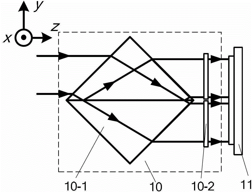
[0047] Specific implementation mode two: the following combination figure 1 , figure 2 and image 3 This embodiment is described. This embodiment is a further description of the first embodiment. The light splitting synchronous phase shift system 10 is composed of a depolarizing beam splitting prism 10-1 and a polarizer group 10-2. The depolarizing beam splitting prism 10-1 is in the form of Cubic structure, the polarizer group 10-2 is composed of two polarizers,

[0048] The incident light beam of the light splitting synchronous phase shifting system 10 is the incident light beam of the depolarizing beam splitting prism 10-1, and the outgoing light beam of the light splitting synchronous phase shifting system 10 is the outgoing light beam of the polarizer group 10-2,

[0049] The depolarizing beam-splitting prism 10-1 splits the incident beam into two beams, and the two beams respectively exit from the two sides of the beam-splitting surface of the depolarizing beam-splitt...

specific Embodiment approach 3

[0052] Specific Embodiment Three: This embodiment is a further description of Embodiment One or Two. The object to be measured 5 is placed in the rectangular window 6, the beam incident side of the rectangular window 6 or the beam exit side of the rectangular window 6, and the object to be measured 5 The length along the arrangement direction of the λ / 4 wave plate 4 is less than or equal to D / 3, and the object 5 to be measured is located directly behind the λ / 4 wave plate 4 in the middle.

[0053] The length of the object to be measured 5 along the arrangement direction of the λ / 4 wave plate 4 can be selected as required, as long as it is less than or equal to D / 3.


PUM


Abstract

The invention discloses a device and method for detecting three-window common-path interference based on a beam splitter prism, belongs to the technical field of interference detection, and solves the problem of low measurement precision in the existing interference detection method. The device comprises a light source, a polarizing film, a collimating beam expansion system, three lambda / 4 wave plates, an object to be detected, a rectangular window, a first lens, a one-dimensional period fiber grating, a second lens, a beam split synchronous phase shift system, an image sensor and a computer, wherein the beam split synchronous phase shift system comprises a depolarization beam splitter prism and a polarizing film set; and the depolarization beam splitter prism is provided with a cube structure. The method comprises the steps as follows: obtaining six interference patterns of the object to be detected through single exposure and collection so as to achieve the purpose of object phase retrieval, and calculating phase distribution phi (x, y) of the object to be detected according to a phase shift angle theta formed by the one-dimensional period fiber grating, wherein the phase retrieval algorithm is simple. The device and the method are suitable for interference detection of the object to be detected.

Description

technical field [0001] The invention relates to a three-window common optical path interference detection device and detection method based on a beam splitting prism, belonging to the technical field of interference detection. Background technique [0002] Optical interferometer is a non-contact, high-precision full-field measurement tool, which is widely used in the detection fields of optical surface, deformation and thickness. Traditional optical interferometry methods include Tieman-Green interferometry, Mach-Zehnder interferometry, and shearing interferometry. Among them, Tieman-Green interferometry, Mach-Zehnder interferometry, etc. use separate optical path interference, that is, the reference beam and measuring beam interfere through different paths, which are easily affected by external vibrations, temperature fluctuations, etc.; shearing interferometry, etc. use common Optical path interference, that is, the reference beam and the measuring beam interfere after pa...

Claims


Application Information

Patent Timeline
Patent Type & Authority Patents(China)
IPC IPC(8): G01B9/02
Inventor 单明广钟志郝本功
Owner HARBIN ENG UNIV
Why Eureka
Try Eureka