Common-path interference detecting device based on beam-split synchronism phase shifting and detecting method

A technology of synchronous phase shifting and interference detection, applied in the direction of measuring devices, optical devices, instruments, etc., can solve the problems of high cost, low measurement accuracy, complicated and difficult operation, etc., and achieve low device cost, simple mapping relationship, and convenient operation flexible effects

Inactive Publication Date: 2014-12-03
HARBIN ENG UNIV
View PDF3 Cites 0 Cited by
  • Summary
  • Abstract
  • Description
  • Claims
  • Application Information

AI Technical Summary

Problems solved by technology

[0005] The purpose of the present invention is to solve the problems that the existing optical phase shift interference detection method is complex and difficult to operate, and requires a high-quality λ / 4 wave plate, high cost, and low measurement accuracy, and provides a common optical path interference based on splitting synchronous phase shift Detection device and detection method

Method used


Image

  • Common-path interference detecting device based on beam-split synchronism phase shifting and detecting method
  • Common-path interference detecting device based on beam-split synchronism phase shifting and detecting method
  • Common-path interference detecting device based on beam-split synchronism phase shifting and detecting method

Examples


specific Embodiment approach 1

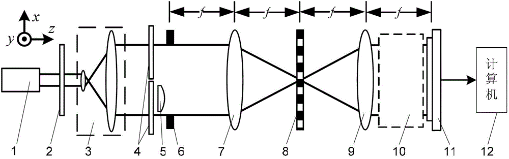
[0036] Specific implementation mode one: the following combination Figure 1 to Figure 5 Describe this embodiment mode, the common optical path interference detection device based on light splitting synchronous phase shift described in this embodiment mode, it comprises light source 1, it also comprises polarizer 2, collimating beam expander system 3, two λ / 4 wave plates 4, The object to be measured 5, the rectangular window 6, the first lens 7, the one-dimensional periodic grating 8, the second lens 9, the light splitting synchronous phase shift system 10, the image sensor 11 and the computer 12, wherein λ is the light wavelength of the light beam emitted by the light source 1,

[0037]The beam emitted by the light source 1 is incident on the light receiving surface of the collimated beam expander system 3 through the polarizer 2, and the outgoing beam after being collimated and expanded by the collimated beam expander system 3 passes through two λ / 4 wave plates 4, to be teste...

specific Embodiment approach 2

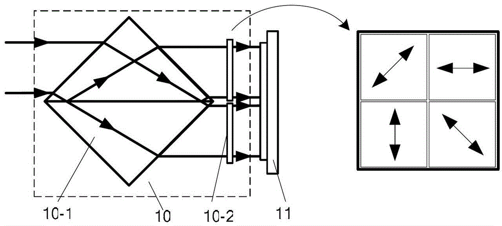
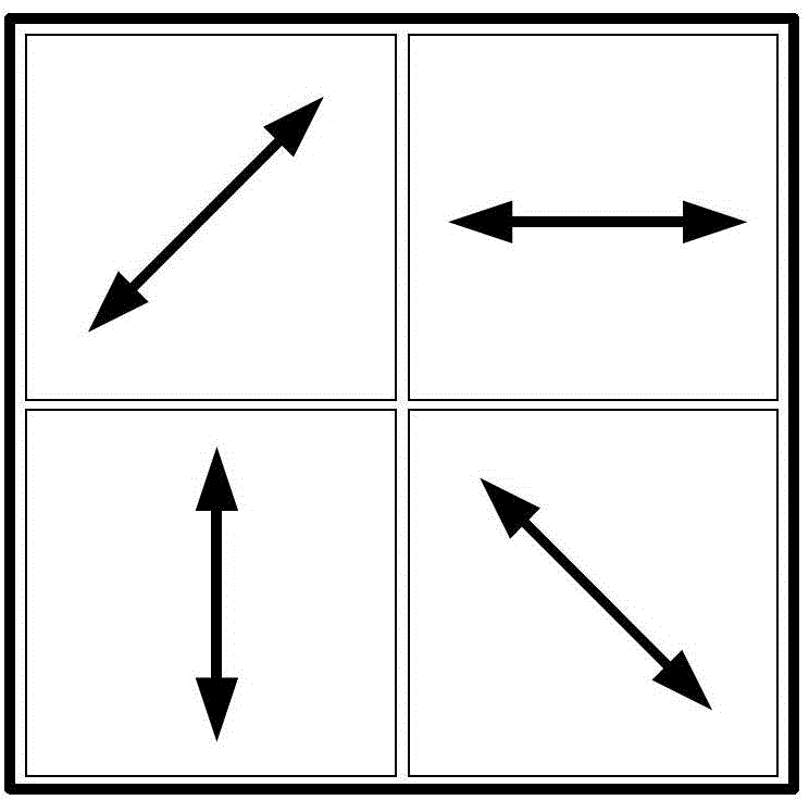
[0046] Specific implementation mode two: the following combination figure 2 and image 3 Describe this embodiment mode, this embodiment mode will further explain Embodiment 1, the light-splitting synchronous phase-shift system 10 is made up of depolarization beam-splitting prism 10-1 and four-quadrant polarizer group 10-2, and described depolarization beam-splitting prism 10-1 presents Cubic structure, the four-quadrant polarizer group 10-2 is composed of four polarizers,

[0047] The incident light beam of the light splitting synchronous phase shifting system 10 is the incident light beam of the depolarized beam splitting prism 10-1, and the outgoing light beam of the light splitting synchronous phase shifting system 10 is the outgoing light beam of the four-quadrant polarizer group 10-2,

[0048] The depolarizing beam splitter 10-1 divides the incident beam into two beams, which are respectively reflected beam and transmitted beam. The reflected beam corresponds to the two...

specific Embodiment approach 3

[0051] Specific Embodiment Three: This embodiment will further illustrate Embodiment One or Two. The object to be measured 5 is placed in the rectangular window 6, the beam incident side of the rectangular window 6 or the beam exit side of the rectangular window 6, and the object to be measured 5 is placed along the rectangular window 6. The length in the x-axis direction is less than or equal to D / 2, and the object 5 to be measured is located directly behind one of the λ / 4 wave plates 4 .

[0052] The length of the object 5 to be measured along the x-axis direction can be selected as required, as long as it is less than or equal to D / 2.


PUM


Abstract

A common-path interference detecting device based on beam-split synchronism phase shifting and a detecting method belong to the field of optical interference detection, and solve the problems that the existing optical phase shifting interference detecting method is complicated and difficult to operate, requires high-quality lambda / 4 wave plates, and has high cost and poor measuring precision. The scheme provided by the invention is as follows: the light beam emitted by a light source is incident to the light receiving surface of a collimating and expanding system through a polaroid, the outgoing beam collimated and expanded by the collimating and expanding system is incident to a first lens through two lambda / 4 wave plates, a to-be-detected object and a rectangular window, the outgoing beam converged by the first lens is incident to a second lens through a one-dimensional periodic grating, the diffracted light beam transmitted by the second lens is incident to a beam-split synchronism phase shifting system, the outgoing beam of the beam-split synchronism phase shifting system is received by the light receiving surface of an image sensor, and the image signal output end of the image sensor is connected with the image signal input end of a computer, so as to obtain the phase distribution of the to-be-detected object.

Description

technical field [0001] The invention relates to a common optical path interference detection device and detection method based on light splitting synchronous phase shift, and belongs to the field of optical interference detection. Background technique [0002] Optical phase shift interferometer is a non-contact, high-precision full-field measurement tool, which is widely used in the detection fields of optical surface, deformation and thickness. Traditional optical interferometry methods include Tieman-Green interferometry, Mach-Zehnder interferometry, and shearing interferometry. Among them, Tieman-Green interferometry, Mach-Zehnder interferometry, etc. use separate optical path interference, that is, the reference beam and measuring beam interfere through different paths, which are easily affected by external vibrations, temperature fluctuations, etc.; shearing interferometry, etc. use common Optical path interference, that is, the reference beam and the measuring beam in...

Claims


Application Information

Patent Timeline
Patent Type & Authority Patents(China)
IPC IPC(8): G01B9/02
Inventor 单明广钟志郝本功
Owner HARBIN ENG UNIV
Why Eureka
Try Eureka