

Container with nozzle capable of preventing liquid leakage
A nozzle and container technology, applied in the field of containers with touching mouths, can solve the problems of inconvenience, dripping on the table or kitchen countertop, liquid residue and so on
- Summary
- Abstract
- Description
- Claims
- Application Information
AI Technical Summary
Problems solved by technology
Method used
Image


Examples
Embodiment Construction
[0015] The technical solutions in the embodiments of the present invention will be described in detail below in conjunction with the accompanying drawings in the embodiments of the present invention. Obviously, the described embodiments are only some of the embodiments of the present invention, not all of them. Based on the embodiments of the present invention, all other embodiments obtained by persons of ordinary skill in the art without making creative efforts belong to the protection scope of the present invention.
[0016] In order to further understand the present invention, the present invention will be described in detail below in conjunction with examples.
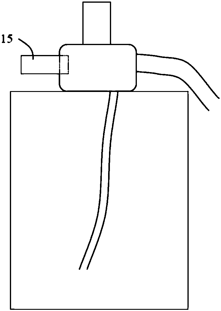
[0017] combine figure 1 and figure 2 As shown, in an embodiment of the present invention, a container with a nozzle for preventing liquid leakage, the container includes a housing cavity 10, a first cavity 12 arranged above the housing cavity 10, and the first cavity The nozzle part 13 connected to the cavity 12...
PUM
 Abstract
Description
Claims
Application Information