
Hydraulic driving rotating disk

A technology for driving discs and turntables, applied in the direction of fluid pressure actuating devices, etc., which can solve the problems of complex hydraulic systems, high costs, and difficulty in applying daily tools

Pending Publication Date: 2018-04-10
ZHEJIANG TENGRONG ENVIRONMENTAL PROTECTION TECH CO LTD
View PDF0 Cites 0 Cited by
  • Summary
  • Abstract
  • Description
  • Claims
  • Application Information

AI Technical Summary

Problems solved by technology

[0002] Hydraulic transmission systems and hydraulic control systems are used in both production and daily life, but the existing hydraulic systems are complicated, have many components, and are expensive, making it difficult to apply them to simple life tools, such as bicycle drives, etc.

Method used


Image

  • Hydraulic driving rotating disk
  • Hydraulic driving rotating disk

Examples


Embodiment Construction

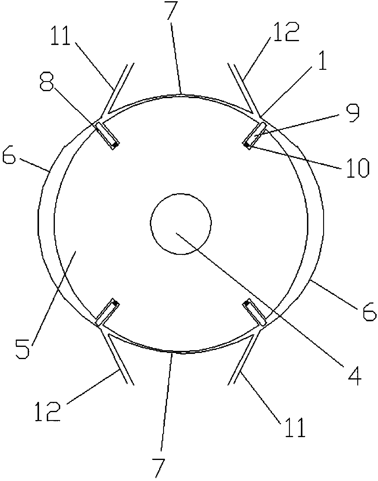
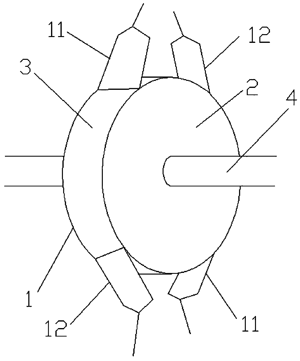
[0014] Combine below figure 1 with figure 2 The technical solution of the present invention will be described in further detail, but not limited to this description.

[0015] A hydraulically driven turntable, comprising an annular side plate 3, cover plates 2 are provided on both sides of the side plate 3, and the two cover plates 2 and the side plates 3 together form a closed casing 1; the two cover plates 2 are Correspondingly, a drive shaft 4 is threaded through the drive shaft 4, and a drive disc 5 is fixedly sleeved on the drive shaft 4. The drive disc 5 is located in the housing 1 and matches the size of the housing 1; the side plate 3 is provided with at least one power unit , the power unit includes a driving section 6 and a traveling section 7, the driving section 6 includes an arc-shaped side plate 3, and there is a gap between the driving section 6 and the driving disc 5; the starting end of the driving section 6 communicates with a liquid inlet pipe 11 , the end...


PUM


Abstract

A hydraulic driving rotating disk comprises an annular side plate; the two sides of the side plate are each provided with a cover plate; the two cover plates and the side plate jointly form a closed shell; a driving shaft is correspondingly and movably connected to the two cover plates in a penetrating manner, and is fixedly sleeved with a driving disk; the driving disk is located in the shell andis matched with the shell in the aspect of size; at least one power unit is arranged on the side plate, and comprises a driving segment and a marching segment; the driving segment comprises an arc-shaped side plate; a gap is reserved between the driving segment and the driving disk; the starting end of the driving segment is communicated with a liquid inflow pipe; the ending end of the driving segment is communicated with a liquid outflow pipe, and is connected with the marching segment; the marching segment comprises an arc-shaped side plate, and is attached to the driving disk; the power unit further comprises a plurality of movable grooves formed in the periphery of the driving disk; a movable plate is movably arranged in the movable grooves; and the length of the movable plate is larger than the gap between the driving segment and the driving disk. The device is simple in structure, small in weight, small in size and convenient to apply.

Description

technical field [0001] The invention relates to the field of driving devices, in particular to a hydraulically driven turntable. Background technique [0002] Hydraulic transmission systems and hydraulic control systems are used in both production and daily life, but the existing hydraulic systems are complicated, have many components, and are expensive, making it difficult to apply them to simple life tools, such as the drive of bicycles. Contents of the invention [0003] In view of the defects in the prior art, the object of the present invention is to provide a hydraulically driven turntable, which has a simple structure, light weight, small volume and is convenient to use. [0004] For achieving above object, the technical scheme that the present invention takes is: [0005] A hydraulically driven turntable, including an annular side plate, cover plates are provided on both sides of the side plate, and the two cover plates and the side plates together form a closed s...

Claims


Application Information

Patent Timeline
IPC IPC(8): F15B15/08
CPCF15B15/08
Inventor 陈永胜
Owner ZHEJIANG TENGRONG ENVIRONMENTAL PROTECTION TECH CO LTD
Learn More