Systems and methods for controlling airflow through a power steering system

A technology of controller and engine speed, applied in power steering mechanism, steering mechanism, engine control and other directions

Active Publication Date: 2021-09-03
FORD GLOBAL TECH LLC
View PDF9 Cites 0 Cited by
  • Summary
  • Abstract
  • Description
  • Claims
  • Application Information

AI Technical Summary

Problems solved by technology

The control valve is further coupled to the cooling fan such that the control valve controls and limits the operation of the cooling fan based on the temperature of the hydraulic fluid

Method used


Image

  • Systems and methods for controlling airflow through a power steering system
  • Systems and methods for controlling airflow through a power steering system
  • Systems and methods for controlling airflow through a power steering system

Examples


Embodiment Construction

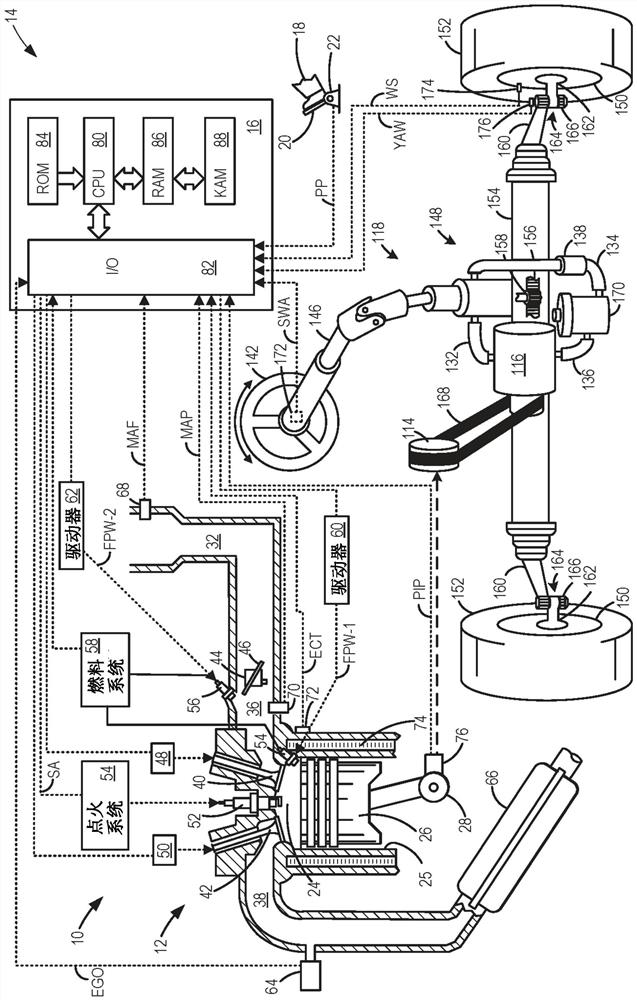
[0016] The following description relates to systems and methods for a vehicle power steering system. More specifically, the description relates to actively mitigating power steering fluid overheating by activating an engine cooling fan based on engine speed and steering wheel angle. Such as figure 1 As shown in , a vehicle power steering system may include a hydraulic steering fluid circuit with a high pressure pump. The high pressure pump may be belt driven and coupled to the vehicle engine as part of the auxiliary drive bracket. Therefore, the pump can rotate at a speed proportional to the rotational speed of the engine, thereby generating heat. Additionally, as the steering wheel angle increases, the pressure in the power steering system can also increase, further increasing the temperature of the steering fluid. The hydraulic power steering fluid circuit may include a cooler configured to reduce the temperature of the steering fluid. However, in response to an increase...


PUM


Abstract

The present application relates to systems and methods for controlling airflow through a power steering system. The present application provides methods and systems for preventing overheating of a power steering system. In one example, a method includes operating an engine cooling fan based on a steering wheel angle and an engine speed. The cooling fan can be operated for a duration based on steering wheel angle and engine speed, eliminating the need for a dedicated power steering coolant temperature sensor.

Description

technical field [0001] The present description generally relates to a hydraulic power steering system for a vehicle. Background technique [0002] Most modern cars are equipped with hydraulic power steering. Hydraulic power steering systems typically include a hydraulic circuit that delivers pressurized fluid (eg, oil) from a reservoir to the steering actuator via a pump mounted on the engine's auxiliary drive. The steering gear uses hydraulic pressure from a pump to assist in turning the vehicle's wheels as the vehicle's steering wheel is moved. The hydraulic power steering system generates heat during this process. When the power steering system overheats, it can cause damage to the power steering pump. [0003] Other attempts to solve overheating problems in hydraulic power steering systems often include adding a power steering fluid cooler to the system. This cooler works by exchanging heat from the fluid into the air, and so conditions with restricted airflow throug...

Claims


Application Information

Patent Timeline
Patent Type & Authority Patents(China)
IPC IPC(8): F01P7/02F02D29/02
CPCF01P7/02F02D29/02F02D31/001B62D5/06B62D5/062F01P1/06F01P3/12F01P7/048F01P7/10F01P7/16F01P2060/08F01P5/02F01P2037/00
Inventor R·V·穆里尔T·G·奥弗利D·柯林斯D·C·彼得里尼
Owner FORD GLOBAL TECH LLC
Why Eureka
Try Eureka