A Method for Realizing Controllable Gap Connection of Hard Materials in Atmospheric Environment

A hard material, atmospheric environment technology, applied in the direction of connecting components, thin plate connections, mechanical equipment, etc., can solve the problems of high vacuum environment requirements, large damage to the material matrix, complex process equipment, etc., to reduce production costs and reduce overheating problems. , The effect of simplifying the process

Active Publication Date: 2015-11-18
HARBIN INST OF TECH SHENZHEN GRADUATE SCHOOL
View PDF6 Cites 0 Cited by
  • Summary
  • Abstract
  • Description
  • Claims
  • Application Information

AI Technical Summary

Problems solved by technology

Mechanical connections mainly include hinged joints and bolted joints. However, the joints obtained by this method have poor strength and tightness, and are difficult to machine and cause great damage to the material matrix. Therefore, they cannot be widely used in occasions that have strict requirements on performance; Due to its high connection quality and reliability, diffusion welding is usually widely used in the field of hard material connection
However, due to the shortcomings of traditional diffusion welding, such as high vacuum environment requirements, complex process equipment and long production cycle, it cannot be well adapted to the modern production development trend of green environmental protection, energy saving and emission reduction; mechanical vibration connection represented by ultrasonic connection method The method is receiving more and more attention because it can realize the connection of materials with simple equipment in a short time; however, traditional mechanical vibration connection methods such as ultrasonic welding also have obvious defects in the mechanical impact damage of the materials to be connected. And it is mostly used for the connection of hard materials and relatively soft metal materials (Al, Cu, Mg, etc.), and the application is subject to certain restrictions.

Method used


Image

  • A Method for Realizing Controllable Gap Connection of Hard Materials in Atmospheric Environment
  • A Method for Realizing Controllable Gap Connection of Hard Materials in Atmospheric Environment
  • A Method for Realizing Controllable Gap Connection of Hard Materials in Atmospheric Environment

Examples


Embodiment 1

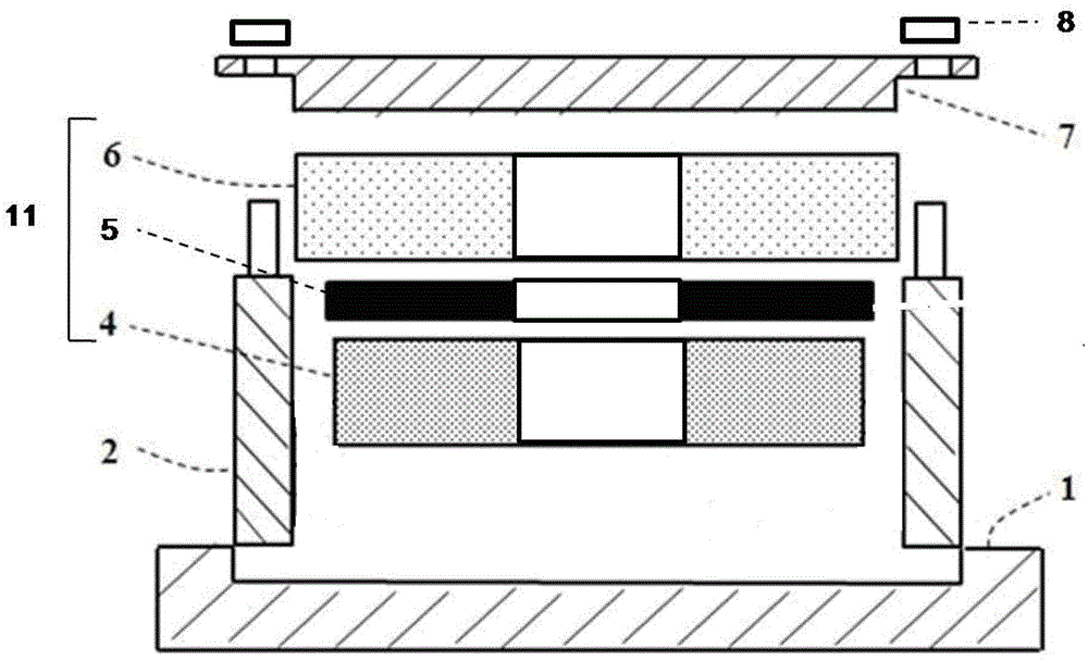
[0066] Embodiment one: see attached figure 1 As shown, a mold, the mold can make the hard material realize the heating and cooling connection with the mold with controllable gap in the atmospheric environment, which includes the mold bottom plate 1, the vertical baffle plate 2, the pressing part 7, and the matching nut part 8. The surrounding vertical baffles 2 are connected to the mold bottom plate 1; the connected workpiece 11 is located on the mold bottom 1 and in the cavity surrounded by the surrounding vertical baffles 2; the pressing member 7 and the vertical baffle 2 For connection, the matching nut piece 8 is used to adjust the pressure of the pressing piece 7 on the workpiece 11 to be connected. Connected workpiece 11: refers to the workpieces that need to be connected together.

[0067] The material of the mold is carbon steel.

[0068] The workpieces 11 to be connected are the same hard material ceramics, which are divided into a base material 4 and a base materia...

Embodiment 2

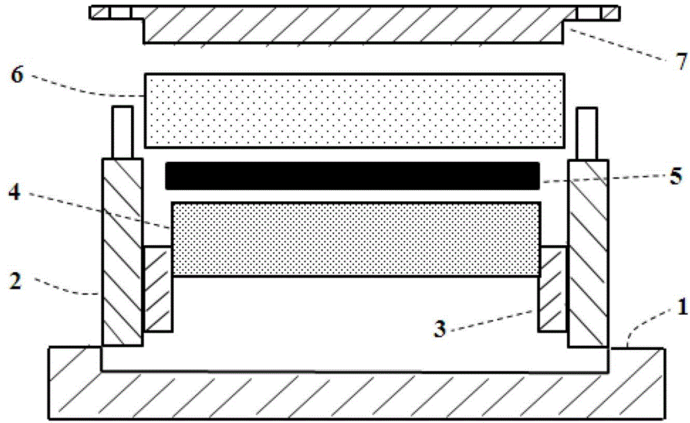
[0075] Embodiment two: see attached figure 2 As shown, a mold, the mold can make the hard material realize the controllable gap heating and cooling connection with the mold in the atmospheric environment, which includes the mold bottom plate 1, the vertical baffle plate 2, the gap control 3, and the pressing part 7 Cooperate with nuts 8, the surrounding vertical baffles 2 are connected around the mold bottom plate 1; the connected workpiece 11 is located on the mold bottom 1 and in the cavity surrounded by the surrounding vertical baffles 2; the gap control 3 is close to On the inner wall of the upright baffle 2, between the upright baffle 2 and the connected workpiece 11, the pressing piece 7 is connected to the upright baffle 2, and the nut 8 is used to adjust the pair of the pressing piece 7 to the connected workpiece 11 pressure sizes.

[0076] The material of the above mold is stainless steel (Cr series).

[0077] The workpiece 11 to be connected includes different har...

Embodiment 3

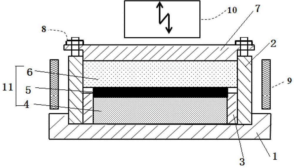
[0086] Embodiment three: see attached image 3 As shown, a mold can make hard materials realize controllable gap heating and cooling connection with the mold in the atmospheric environment, which includes a mold bottom plate 1, a vertical baffle 2, a gap control 3, and a pressing piece 7 , cooperate with the nut 8, the surrounding vertical baffles 2 are connected to the mold bottom plate 1, and the connected workpiece 11 is located on the mold bottom 1 and in the cavity surrounded by the surrounding vertical baffles 2; the gap control 3 is close to the vertical The inner wall of the baffle 2 is located between the upright baffle 2 and the connected workpiece 11, the pressing piece 7 is connected to the upright baffle 2, and the nut 8 is used to adjust the pressure of the pressing piece 7 to the connected workpiece 11. Pressure size.

[0087] The material of the above mold is two kinds of stainless steel (Mo series) or alloy steel.

[0088] The workpiece 11 to be connected in...


PUM

PropertyMeasurementUnit
thicknessaaaaaaaaaa

Abstract

The invention provides a method for implementing controllable gap connection of hard materials in atmospheric environment by heating and cooling with mould and a mould applied in the method. The hard materials to be connected include ceramic, glass and other hard materials. The method based on the existing mechanical vibration connection methods, such as ultrasonic-assisted connection, is characterized in that a special clamping mould is used, overall heating and cooling with mould is applied, and the method is organically used with high frequency vibration assisted connection to allow for reliable connection of hard materials in atmospheric environment. Using the special clamping mould has the advantages that connecting process devices are simplified, operation is simple; the materials to be connected are clamped to ensure stability of overall structure; gap between joint surfaces is controlled; sufficient pre-pressure is provided; the clamping mould serves as an indirect heating source to input sufficient heat for joints; cooling rate is retarded; separation of the connected workpieces is simplified.

Description

technical field [0001] The present invention relates to a method for connecting hard materials with controllable gaps through mold heating and cooling in an atmospheric environment and a mold used in the method, in particular to a fast, Efficient and strong connection method. Background technique [0002] With the advancement of science and technology and the development of social production, hard materials such as ceramics (oxide ceramics, nitride ceramics, boride ceramics, carbide ceramics, etc.), glass (oxide glass and non-oxide glass) and metal compounds or minerals Such materials have been widely used because of their excellent properties. Ceramics are widely used in materials engineering, electronic engineering, chemical engineering and mechanical engineering because of their excellent performance in terms of electrical properties, chemical properties, optical properties and heat resistance, which metals and other polymer materials cannot do. Especially in aerospace,...

Claims


Application Information

Patent Timeline
Patent Type & Authority Patents(China)
IPC IPC(8): F16B5/00F16B5/02
Inventor 计红军李明雨程晓
Owner HARBIN INST OF TECH SHENZHEN GRADUATE SCHOOL
Why Eureka
Try Eureka