Control force adjusting device

A technology for adjusting devices and operating forces, applied in the field of operating systems, can solve problems such as uneven friction, harmful deformation and tilting of gradient springs, and small adjustment space, so as to reduce processing tolerance and assembly difficulty, and reduce harmful deformation and tilting Turn, increase the effect of adjustment accuracy

Active Publication Date: 2018-05-18
CHINA HELICOPTER RES & DEV INST
View PDF8 Cites 2 Cited by
  • Summary
  • Abstract
  • Description
  • Claims
  • Application Information

AI Technical Summary

Problems solved by technology

[0004] However, in the actual application of the above-mentioned control force adjustment device, there will be the following problems: first, the pre-tightening force of the locking bolts on the upper and lower plates of the friction ring is difficult to determine, the adjustment space is small, and the accuracy is poor, and it is difficult to meet the uniform friction requirement ;
[0005] Second, due to the existence of machining errors in the roundness and coaxiality of one end of the torsion shaft and the large error of the friction plate attached to this end, the friction ring’s holding force on the torsion shaft is uneven under a large preload, and then Result in uneven friction, and there are stuck, astringent and stagnant phenomena;
[0006] Third, because there are only a few adjustment holes on the adjustment plate, the adjustment is not fine enough, and it is difficult to meet the gradient requirements of the steering force; fourth, since the adjustment plate has no axial and radial restraint effects on the gradient spring, during the movement of the torsion shaft Detrimental deformation and tilting of gradient springs in

Method used


Image

  • Control force adjusting device
  • Control force adjusting device
  • Control force adjusting device

Examples


Embodiment Construction

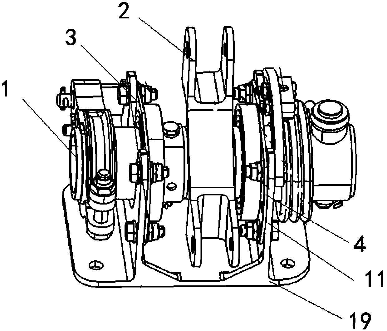
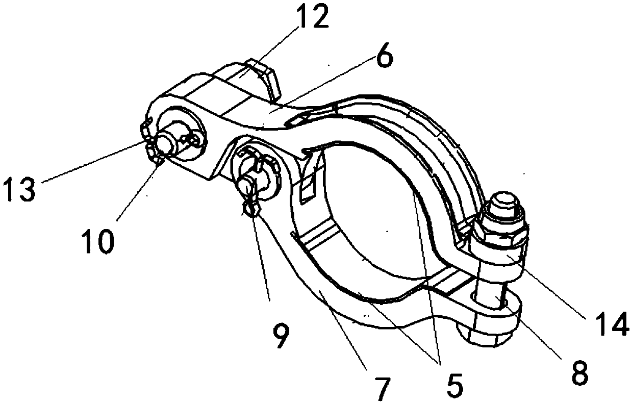
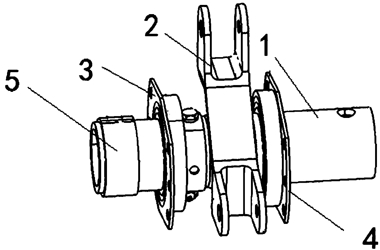
[0038] In order to make the objectives, technical solutions and advantages of the present invention clearer, the technical solutions in the embodiments of the present invention will be described in more detail below in conjunction with the drawings in the embodiments of the present invention. In the drawings, the same or similar reference numerals denote the same or similar elements or elements having the same or similar functions throughout. The described embodiments are some, but not all, embodiments of the invention. The embodiments described below by referring to the figures are exemplary and are intended to explain the present invention and should not be construed as limiting the present invention. Based on the embodiments of the present invention, all other embodiments obtained by persons of ordinary skill in the art without creative efforts fall within the protection scope of the present invention. Embodiments of the present invention will be described in detail below ...


PUM


Abstract

The invention discloses a control force adjusting device and belongs to the technical field of control systems. The control force adjusting device comprises a friction assembly, a torsion transfer assembly, a gradient adjusting assembly and a mounting support. The mounting support is composed of a bottom plate and fixing mounting plates arranged on the left side and the right side. The torsion transfer assembly is provided with a torsion shaft, a rocker, a left axial rotary supporting element, a right axial rotary supporting element and a friction plate, wherein the rocker is fixed to the middle portion of the torsion shaft, the left axial rotary supporting element is arranged on the left side of the rocker, the right axial rotary supporting element is arranged on the right side of the rocker, and the left axial rotary supporting element and the right axial rotary supporting element are fixed to the fixing mounting plates. The two ends of the torsion shaft penetrate through the mounting support to be connected with the friction assembly and the gradient adjusting assembly separately. The friction assembly can adjust the clamping force of one end of the torsion shaft. The gradient adjusting assembly can adjust the gradient force of the torsion shaft by adjusting the mounting position of a torsion spring of the gradient adjusting assembly. Control force enters the adjusting device via the input end of the rocker, and is output from the output end of the rocker after being adjusted.

Description

technical field [0001] The invention belongs to the technical field of steering systems, and in particular relates to a steering force adjusting device. Background technique [0002] The control force adjustment device is used in the control system and control system of the vehicle, especially in the control system and flight control system of the aircraft (helicopter, fixed-wing aircraft, etc.), so as to provide the driver with a good control feeling. [0003] The structure of the known general steering force adjustment device is composed of friction rings, friction plates, torsion shafts, gradient springs, gradient adjustment plates, flange bearings and supports, pads, mounting blocks, connectors and the like. The torsion shaft is installed on the support through flange bearings and bolts, one end of the torsion shaft is attached with a friction plate, and the other end is installed with a gradient spring. One end of the friction ring is installed on the support by bolts,...

Claims


Application Information

Patent Timeline
Patent Type & Authority Applications(China)
IPC IPC(8): F16D23/12
Inventor 王景山白一尚邓海侠
Owner CHINA HELICOPTER RES & DEV INST
Why Eureka
Try Eureka