Check patentability & draft patents in minutes with Patsnap Eureka AI!

Liquid crystal phase shifter, phase shifting method and manufacturing method thereof

A phase shifter and liquid crystal technology, applied in the direction of instruments, optics, optical components, etc., can solve the problems of reducing the phase shift degree of the phase shifter, the length of the phase shifter, and the decrease of the dielectric constant, so as to achieve the increase of the phase shift degree, The principle is clear and the effect of reducing loss

Active Publication Date: 2020-08-25
BOE TECH GRP CO LTD
View PDF7 Cites 0 Cited by
  • Summary
  • Abstract
  • Description
  • Claims
  • Application Information

AI Technical Summary

Problems solved by technology

Liquid crystal phase shifters have great advantages in continuous phase modulation, but due to the small dielectric constant of liquid crystals, they cannot meet the requirements of phase modulation well, so it is necessary to extend the microstrip line to meet the requirements of phase modulation
[0003] Due to the limitation of the dielectric constant of the liquid crystal itself, the liquid crystal phase shifter must be made long enough to achieve a satisfactory degree of phase shift, and the phase shifter is too long, which not only increases the loss, but also increases its volume and weight
[0004] Traditional liquid crystal phase shifters such as figure 1 As shown, the dielectric constant of the liquid crystal layer is the same everywhere, and the dielectric constant of the two liquid crystals after mixing is smaller than the sum of the dielectric constants before mixing, because the dielectric constant in the mixed crystal changes linearly, that is, ε=c 1 ×ε 1 +c 2 ×ε 2 Among them, c is the concentration, ε is the dielectric constant, so when the liquid crystals are mixed with each other, the dielectric constant will decrease, thereby reducing the phase shift degree of the phase shifter

Method used


Image

  • Liquid crystal phase shifter, phase shifting method and manufacturing method thereof
  • Liquid crystal phase shifter, phase shifting method and manufacturing method thereof
  • Liquid crystal phase shifter, phase shifting method and manufacturing method thereof

Examples


Embodiment Construction

[0040] In order to illustrate the present invention more clearly, the present invention will be further described below in conjunction with preferred embodiments and accompanying drawings. Similar parts in the figures are denoted by the same reference numerals. Those skilled in the art should understand that the content specifically described below is illustrative rather than restrictive, and should not limit the protection scope of the present invention.

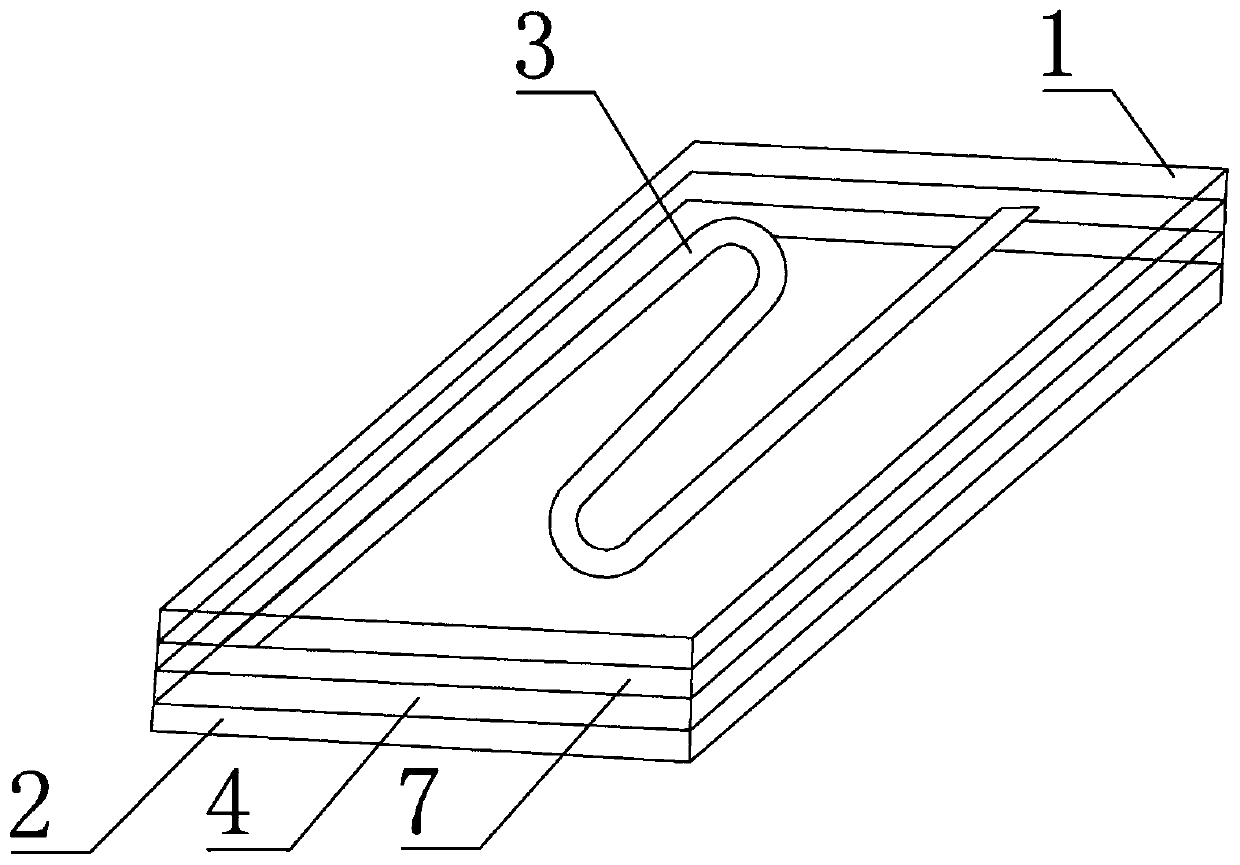
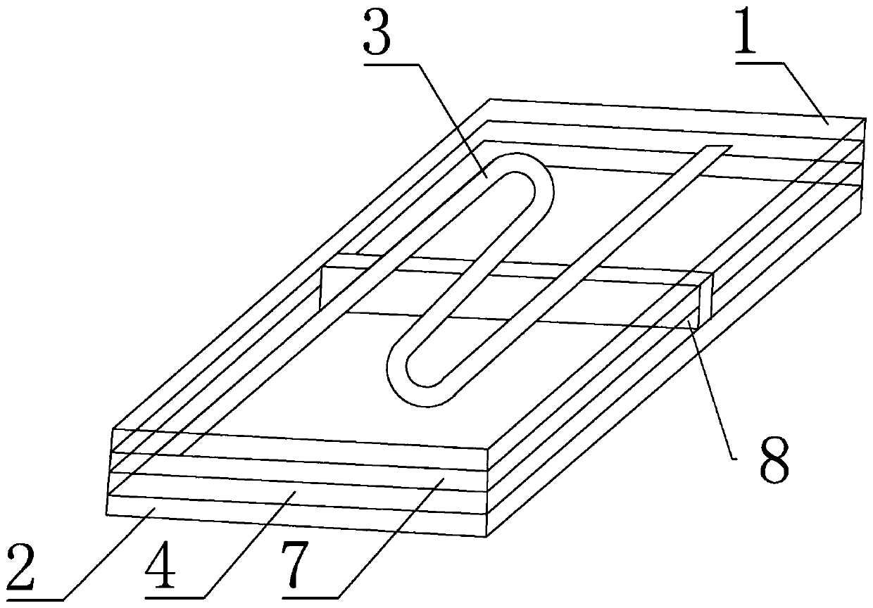
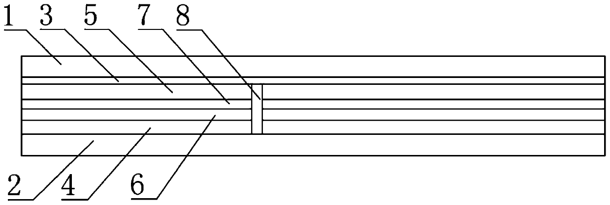
[0041] Such as figure 2 As shown, a liquid crystal phase shifter, the phase shifter includes a first substrate 1 and a second substrate 2 arranged in a box; a first electrode layer 3 arranged on the side of the first substrate 1 facing the second substrate 2; On the side of the second substrate 2 facing the first substrate 1, a second electrode layer 4 comprising a plurality of electrically isolated electrode plates; a plurality of isolation strips 8 arranged between the first electrode layer 3 and the second substrate 2,...


PUM


Abstract

The invention discloses a liquid crystal phase shifter, a phase shifting method and a manufacturing method thereof. The phase shifter includes a first substrate and a second substrate arranged opposite to each other; and is arranged on the side of the first substrate facing the second substrate a first electrode layer; a second electrode layer comprising a plurality of electrically isolated electrode plates disposed on the second substrate facing the first substrate; disposed on the first electrode layer and the second substrate A plurality of isolation strips between them, the plurality of isolation strips and the first electrode layer, the second electrode layer and the liquid crystal layer in between are formed into a plurality of mutually independent sealing areas, each of the electrode plates corresponds to one of the The sealed area, in which liquid crystals with different dielectric constants are sealed. The invention increases the phase shift degree of the liquid crystal phase shifter.

Description

technical field [0001] The invention relates to the field of display technology, in particular to a liquid crystal phase shifter, a phase shifting method and a manufacturing method thereof. Background technique [0002] A phase shifter is a device that can adjust the phase of a wave. It is widely used in the fields of radar, missile attitude control, accelerator, communication, instrumentation and even music. Liquid crystal phase shifters have great advantages in continuous phase modulation, but due to the small dielectric constant of liquid crystals, they cannot meet the requirements of phase modulation well, so it is necessary to extend the microstrip line to meet the requirements of phase modulation. [0003] Due to the limitation of the dielectric constant of the liquid crystal itself, the liquid crystal phase shifter must be made long enough to achieve a satisfactory degree of phase shift, and the phase shifter is too long, which not only increases the loss, but also in...

Claims


Application Information

Patent Timeline
Patent Type & Authority Patents(China)
IPC IPC(8): G02F1/13G02F1/1333G02F1/1343G02F1/1337
CPCG02F1/1313G02F1/133377G02F1/1337G02F1/1343G02F1/13306G02B26/06G02F1/134309G02F2203/50G02F1/1339G02F1/13378
Inventor 刘明星张鹏举朱红苗浩孙海雁李锐
Owner BOE TECH GRP CO LTD
Features
  • R&D
  • Intellectual Property
  • Life Sciences
  • Materials
  • Tech Scout
  • Unparalleled Data Quality
  • Higher Quality Content
  • 60% Fewer Hallucinations
Learn More