Combined head and ray imaging device

A technology of radiographic imaging and handpiece, applied in X-ray equipment, X-ray tube cooling, X-ray tube electrodes, etc., can solve the problems of X-ray machine damage, anode rake surface damage, limited anode rake surface bearing capacity, etc. The effect of uniform temperature gradient distribution

Active Publication Date: 2018-07-06
SUZHOU POWERSITE ELECTRIC CO LTD
View PDF4 Cites 4 Cited by
  • Summary
  • Abstract
  • Description
  • Claims
  • Application Information

AI Technical Summary

Problems solved by technology

When the X-ray tube generates X-rays, only about 1% of the energy is converted into X-rays, and more than 99% of the energy is converted into heat energy and gathered on the anode rake surface, and the anode rake surface has a limited ability to withstand heat energy , if the heat energy cannot be conducted in time, when the accumulated heat energy exceeds the bearing capacity of the anode of the X-ray tube, the anode surface will be damaged, thus guiding the X-ray machine to damage

Method used


Image

  • Combined head and ray imaging device
  • Combined head and ray imaging device
  • Combined head and ray imaging device

Examples


Embodiment 1

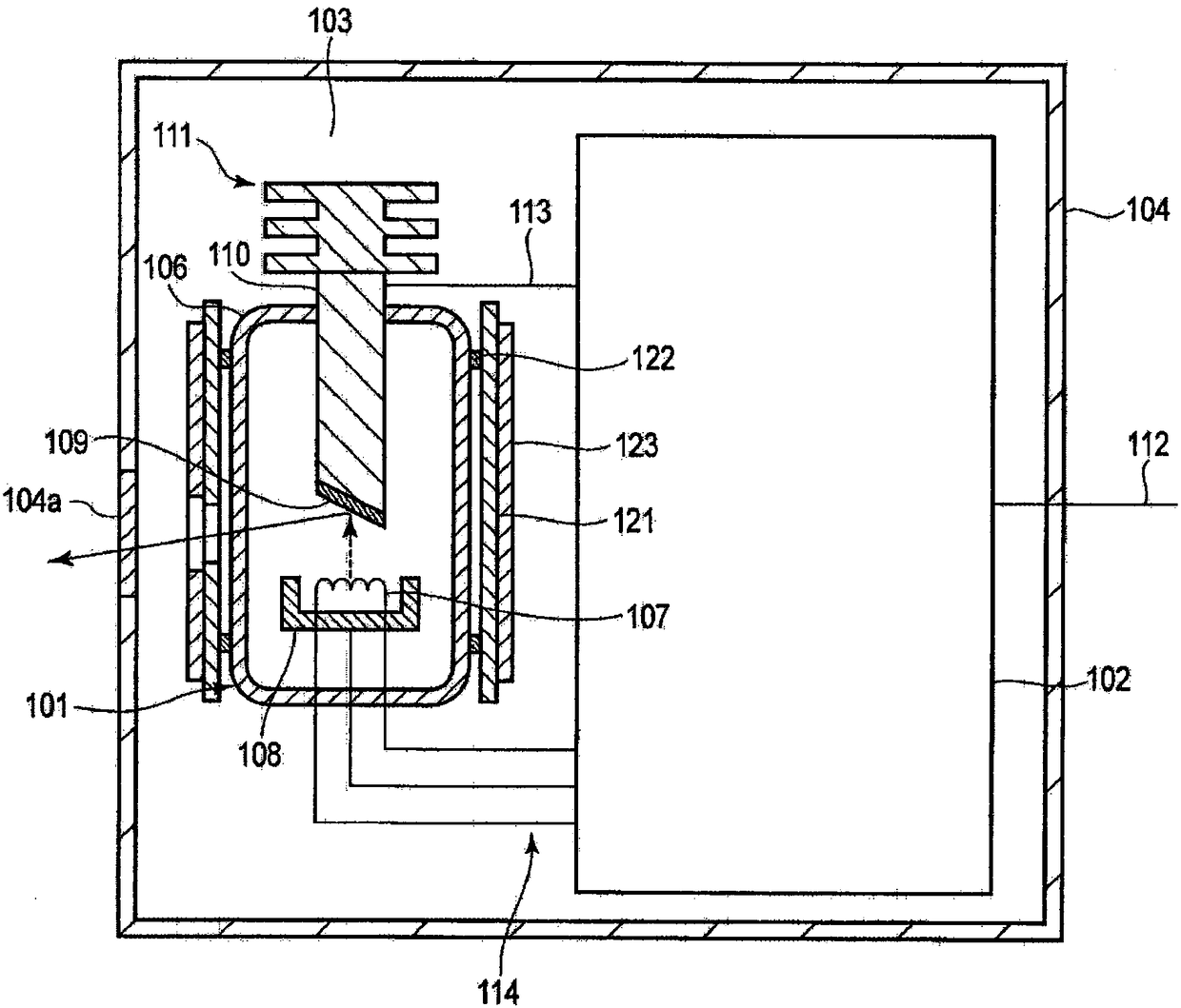
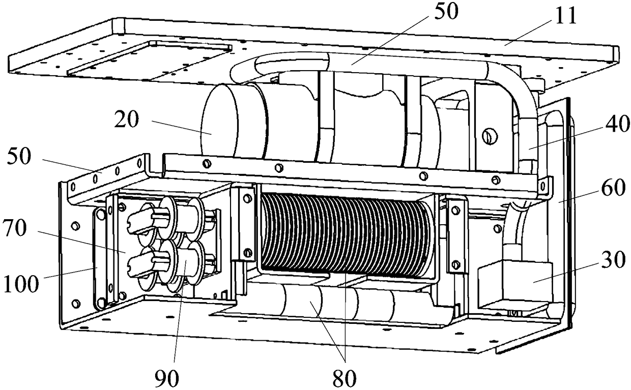
[0031] The embodiment of the present invention provides a combined head, such as figure 2 As shown, the combined handpiece includes a casing 10 , a ray tube 20 , a pump body 30 and a tube body 40 . The casing 10 has a sealed cavity, and the ray tube 20 , the pump body 30 and the tube body 30 are arranged in the sealed cavity. When the combined handpiece is actually used, the sealed cavity will be filled with a flowable insulating medium.

[0032] Such as figure 2 As shown, the pump body 30 can be arranged on the side away from the anode of the ray tube 20 , one end of the tube body 40 is connected to the outlet of the pump body 30 , and the other end extends to the vicinity of the anode of the ray tube 20 . The other end of the pipe body 40 and the inlet of the pump body 30 are soaked in the insulating medium. The temperature difference between the insulating medium at the position far away from the anode of the ray tube 20 and the temperature of the insulating medium nea...

Embodiment 2

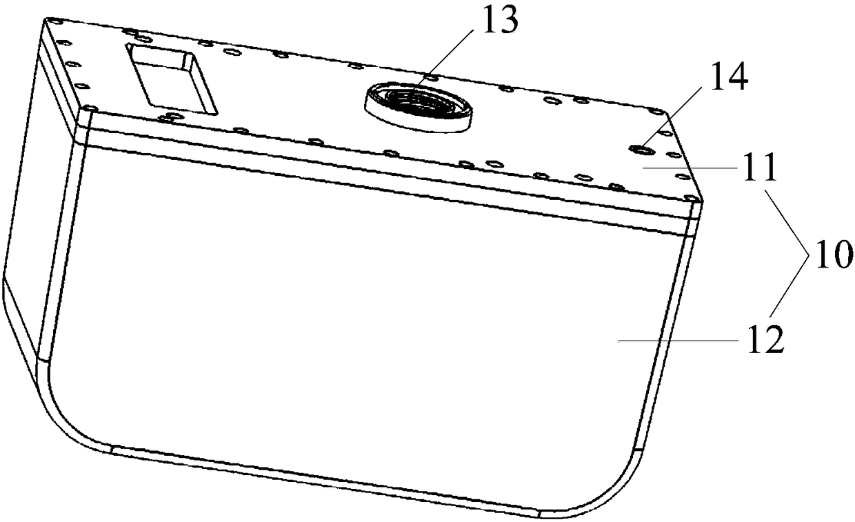
[0039] The embodiment of the present invention provides a combined head, the difference from the first embodiment is that, as figure 2 and image 3 As shown, the housing 10 includes a cover plate 11 and a housing body 12 . The combined head also includes a first insulating partition 50 . The first insulating partition 50 is arranged in the sealed cavity, and the sealed cavity is divided into a connected first cavity and a second cavity, the cover plate 11 is arranged on the side wall of the first cavity, and the ray tube 20 is arranged on In the first cavity, the pump body 30 is arranged on the side away from the anode of the ray tube 20 in the second cavity. Such as figure 2 and Figure 4 As shown, the cover plate 11 is provided with a first opening 13, and a transparent cover is sealed on the first opening 13. The ray exit surface of the ray tube 20 corresponds to the position of the transparent cover, that is, the first opening serves as the exit of the ray. window. ...

Embodiment 3

[0055] An embodiment of the present invention provides a radiographic imaging device, including the combination head described in Embodiment 1 or Embodiment 2 and any optional implementation manner thereof.

[0056] Optionally, the radiographic equipment is a C-arm X-ray machine.


PUM


Abstract

The invention discloses a combined head and a ray imaging device. The combined head comprises a casing, a ray tube, a pump and a tube, wherein the casing is provided with a sealed cavity, the ray tubeis arranged in the sealed cavity, the pump and the tube are arranged in the sealed cavity, the pump is arranged at one side away from the positive pole of the ray tube, one end of the tube is connected with an outlet of the pump while the other end thereof extends to the position near the positive pole of the ray tube, or, the pump is arranged near the positive pole of the ray tube, one end of the tube is connected with an inlet of the pump while the other end thereof extends to the side way from the positive pole of the ray tube. An insulating medium at the position away from the positive pole can be pumped to the position near the positive pole, the insulating medium in the sealed cavity can be driven to form a cycle, and thus, temperature difference between the position of the positivepole and other positions can be reduced greatly, and temperature graded distribution of the insulating medium in the sealed cavity can be more uniform.

Description

technical field [0001] The invention relates to the technical field of medical equipment, in particular to a combined machine head and radiographic imaging equipment. Background technique [0002] The combined head includes a ray tube for generating rays, for example, the X-ray tube in the X-ray combined head is used for generating X-rays. The combined head is usually assembled with an image sensor such as a CCD, a processor, and a bracket to form a complete X-ray machine product, such as a C-arm X-ray machine, which is widely used in fluoroscopy in medical operations. The structure of the X-ray combination head adopting the fixed anode X-ray tube in the prior art is as follows: figure 1 As shown, the housing 104 is provided with an X-ray tube 101 and a high-voltage generator 102 providing high voltage for the X-ray tube 101 , and the housing 104 is filled with insulating oil 103 . The X-ray tube 101 includes a vacuum envelope 106 , a cathode filament 107 arranged in the v...

Claims


Application Information

Patent Timeline
Patent Type & Authority Applications(China)
IPC IPC(8): H01J35/12
CPCH01J35/12H05G1/025H05G1/06H01J2235/1204H01J2235/125H05G1/20
Inventor 王维重何杰黄强
Owner SUZHOU POWERSITE ELECTRIC CO LTD
Why Eureka
Try Eureka