Reinforced heat transfer pipe with spinning disks

A technology of swirl sheets and heat transfer tubes, which is applied in the field of enhanced heat transfer tubes, can solve the problems of poor spin flow continuity, spiral flow and spin flow strength, etc., to achieve enhanced tangential motion, good continuity, and manufacturing low cost effect

Active Publication Date: 2014-07-16
CHINA PETROLEUM & CHEM CORP +1
View PDF6 Cites 0 Cited by
  • Summary
  • Abstract
  • Description
  • Claims
  • Application Information

AI Technical Summary

Problems solved by technology

[0004] The purpose of the present invention is to provide a kind of enhanced heat transfer tube with swirl fins, to solve the problem of fluid formed when the flow rate of the fluid in the heat transfer tube body is low in existing enhanced heat transfer tubes with swirl fins. The strength of the helical flow and the spin flow is weak, and the continuity of the spin flow is poor

Method used


Image

  • Reinforced heat transfer pipe with spinning disks
  • Reinforced heat transfer pipe with spinning disks
  • Reinforced heat transfer pipe with spinning disks

Examples


Embodiment

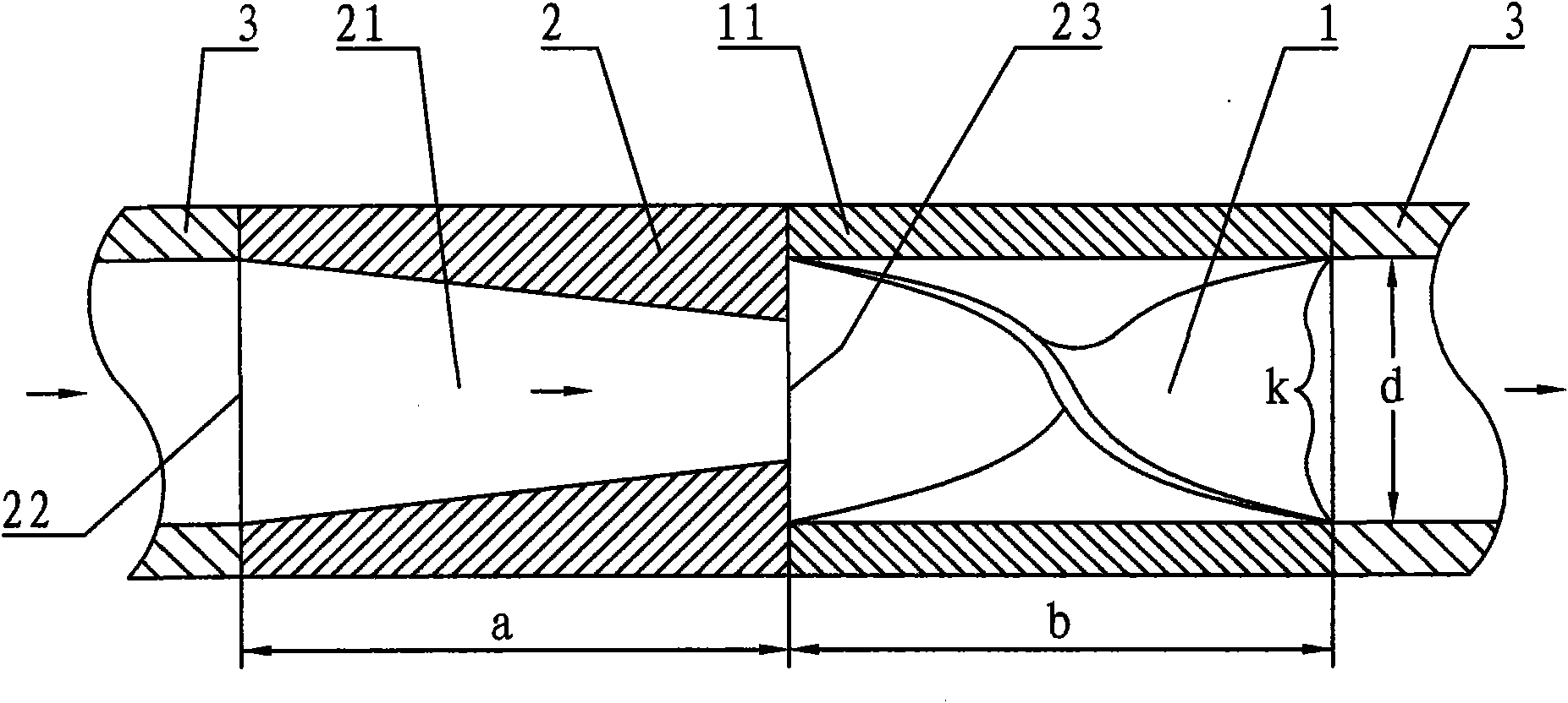
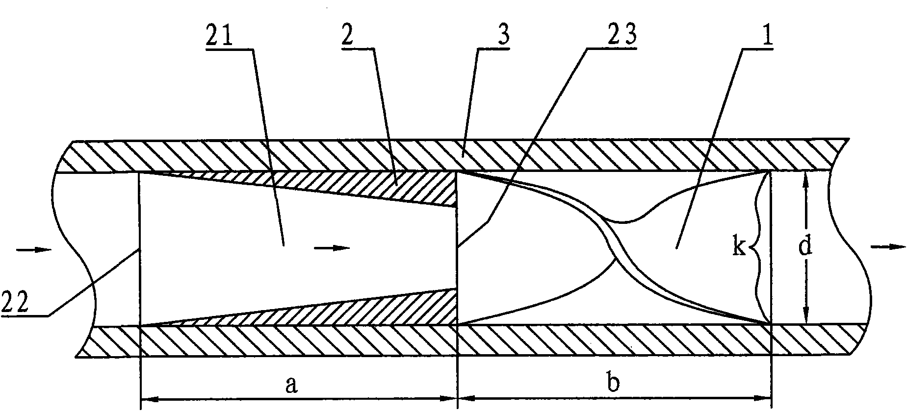
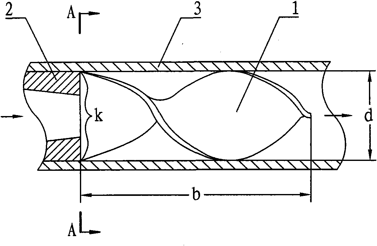
[0029] The first enhanced heat transfer tube of the present invention is tested in the laboratory; see Figure 5 ,as well as figure 1 , image 3 , Figure 4 and related text descriptions. The enhanced heat transfer tube is provided with two swirl fin tube-shrink tube assemblies with the same structural parameters, one of which is arranged at the inlet section of the enhanced heat transfer tube; the distance t between the two swirl fin tube-shrink tube assemblies is 1350 mm. The heat transfer pipe body 3 is a light pipe; the outer diameter of the heat transfer pipe body 3 is 60 millimeters (the outer diameter of the shrink tube and the swirl sheet pipe body are equal to it), and the inner diameter d of the heat transfer pipe body 3 is 50 millimeters ( The diameter of the inlet of the shrink tube lumen and the inner diameter of the swirl sheet body are equal to it). The length a of the shrink tube is twice (100 mm) the inner diameter d of the heat transfer tube body 3 . The...


PUM


Abstract

The invention discloses a reinforced heat transfer pipe with spinning disks, aiming to solve the problems of weaker strength of spiral flow and spin flow and poorer continuity of the spin flow of fluid when the fluid in a heat transfer pipe body of the traditional reinforced heat transfer pipe with the spinning disk is lower in flow velocity. The reinforced heat transfer pipe disclosed by the invention comprises a heat transfer pipe body (3) and a plurality of spinning disks (1) arranged along the axial direction of the reinforced heat transfer pipe at interval, wherein a spinning disk-shrinkage pipe assembly constituted by one shrinkage pipe (2), one spinning disk (1) and one shrinkage pipe (2) is arranged in front of each spinning disc (1). Each shrinkage pipe (2) is provided with a truncated-cone-shaped inner cavity (21), two ends of each inner cavity (21) are respectively an inner-cavity inlet (22) and an inner-cavity outlet (23), and the area of each inner-cavity outlet (23) is smaller than that of each inner-cavity inlet (22). Each inner-cavity outlet (23) is adjacent to the front end of the corresponding spinning disc (1). The reinforced heat transfer pipe with the spinning disks is mainly applied to tubular heat exchangers of industries, such as the petrochemical industry and the coal chemical industry.

Description

technical field [0001] The invention relates to an enhanced heat transfer tube, in particular to an enhanced heat transfer tube with swirl fins. Background technique [0002] In the tubular heat exchangers in the petrochemical industry, the enhanced heat transfer tubes used mainly include the following types: (1) Spiral grooved tubes. The characteristic is that the rough rib surface of the tube wall destroys the boundary layer of the fluid, and promotes the turbulent flow of the boundary fluid to enhance heat transfer. The disadvantage is that the convective heat transfer to the fluid in the central area of ​​the heat transfer pipe body is difficult to strengthen. (2) Spoiler tube. Insert a turbulent (twisted belt or twisted iron) into the heat transfer tube; the fluid spirals in the heat transfer tube to generate centrifugal force, and the centrifugal force causes disturbance between the fluids and radial convection, which promotes the thinning of the boundary layer of th...

Claims


Application Information

Patent Timeline
Patent Type & Authority Patents(China)
IPC IPC(8): F28F1/00F28F13/12F28F13/02
Inventor 高晓红孙志钦黄进焕高耀成王作红
Owner CHINA PETROLEUM & CHEM CORP
Why Eureka
Try Eureka