
Efficient energy-saving annealing-free cold heading steel device

A high-efficiency, energy-saving, annealing-free technology, applied in the field of cold heading steel, can solve the problems of high energy consumption for processing steel, inability to use heat uniformly, and inconsistent heat sources

Active Publication Date: 2021-01-01
SANMING UNIV
View PDF7 Cites 0 Cited by
  • Summary
  • Abstract
  • Description
  • Claims
  • Application Information

AI Technical Summary

Problems solved by technology

The above-mentioned patents have the following disadvantages: steel heating generally requires an annealing process to eliminate internal stress, and annealing requires reheating of cast steel. For general processing equipment, the heat sources required for annealing and melting are inconsistent, or the heat cannot be used uniformly. Lead to higher energy consumption for processing steel

Method used


Image

  • Efficient energy-saving annealing-free cold heading steel device
  • Efficient energy-saving annealing-free cold heading steel device
  • Efficient energy-saving annealing-free cold heading steel device

Examples


Embodiment Construction

[0028] The technical solution of this patent will be further described in detail below in conjunction with specific embodiments.

[0029] Embodiments of the present patent are described in detail below, examples of which are shown in the drawings, wherein the same or similar reference numerals designate the same or similar elements or elements having the same or similar functions throughout. The embodiments described below by referring to the figures are exemplary and are only used for explaining the patent, and should not be construed as limiting the patent.

[0030] In the description of this patent, it is to be understood that the terms "center", "upper", "lower", "front", "rear", "left", "right", "vertical", "horizontal", The orientation or positional relationship indicated by "top", "bottom", "inner", "outer", etc. is based on the orientation or positional relationship shown in the drawings, and is only for the convenience of describing this patent and simplifying the des...


PUM


Abstract

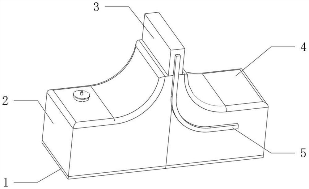
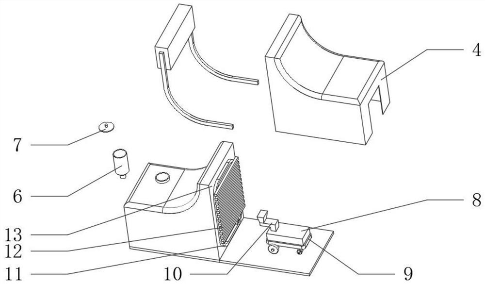
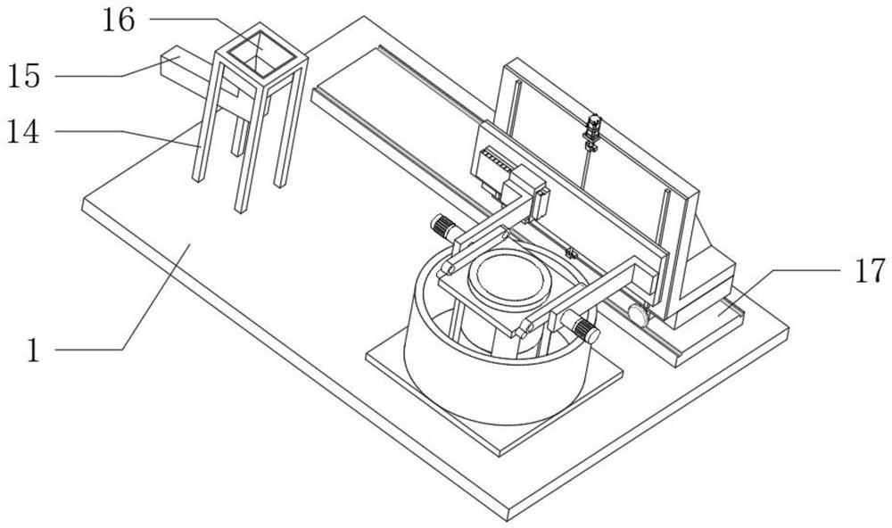
The invention discloses an efficient energy-saving annealing-free cold heading steel device, and relates to the technical field of cold heading steel. The efficient energy-saving annealing-free cold heading steel device aims to solve the problem that energy consumption is too high due to the fact that heat cannot be uniformly utilized. The efficient energy-saving annealing-free cold heading steeldevice specifically comprises a first bottom plate, wherein a second bottom plate is fixedly connected to the outer wall of one side of the first bottom plate; a first cover shell is fixedly connectedto the outer wall of the top of the first bottom plate; a feeding cylinder is fixedly connected to the outer wall of the top of the first cover shell; a material cover is movably connected to the outer wall of the top of the feeding cylinder; a second cover shell is fixedly connected to the outer wall of the top of the second bottom plate; arc-shaped plates and platform plates are arranged insidethe first cover shell and the second cover shell; a vertical plate is arranged on the outer wall of the right side of the first cover shell; a discharging hole is formed in the inner wall of the vertical plate; a discharging pipe is welded to the inner wall of the discharging hole; an annular pipe is fixedly connected to the outer wall of one side of the vertical plate; the annular pipe is made of a heat conduction material; and a transverse pipe is fixedly connected to the outer wall of one side of the annular pipe. According to the efficient energy-saving annealing-free cold heading steel device, the heat of a closed space can be reused, the necessity of reheating in the annealing process is avoided, and the double functions of heating close to the transverse pipe and cooling away fromthe transverse pipe at a constant speed are achieved.

Description

technical field [0001] The invention relates to the technical field of cold heading steel, in particular to a high-efficiency, energy-saving and annealing-free cold heading steel device. Background technique [0002] In the existing cold heading steel production process, most of the optimization methods focus on formula improvement, but the processing process of cold heading steel has extremely strict requirements on impurity content, so avoiding the entry of external impurities in the production process will be the key to the production of cold heading steel. key. [0003] After searching, the Chinese patent application number is 201921045274.7, which discloses a cold heading stainless steel blind rivet production equipment, including legs. The main body of the machine, the two sides of the main body of the cold heading machine are respectively symmetrically provided with limit card slots, and the top of the limit card slots is rectangularly distributed with fixed rods, th...

Claims


Application Information

Patent Timeline
IPC IPC(8): B22D47/00B22D35/04F27B14/08F27B14/14
CPCB22D47/00B22D35/04F27B14/08F27B14/14
Inventor 吴龙高浩黄标彩张璐邱思杰
Owner SANMING UNIV
Learn More