Demoulding structure

A technology of demolding and master mold, applied in the field of mold release structure, can solve problems such as sticking master mold, and achieve the effect of solving sticking master mold

Active Publication Date: 2018-07-24
SUZHOU MITAC PRECISION TECH
View PDF3 Cites 4 Cited by
  • Summary
  • Abstract
  • Description
  • Claims
  • Application Information

AI Technical Summary

Problems solved by technology

[0005] Therefore, the object of the present invention is to provide a demoulding structure. When the demoulding structure is formed on the side of the master mold and the appearance surface is a product with a high mirror surface, it can not only solve the problem of the product sticking to the master mold, but also make the appearance surface. high mirror

Method used


Image

  • Demoulding structure
  • Demoulding structure
  • Demoulding structure

Examples


Embodiment Construction

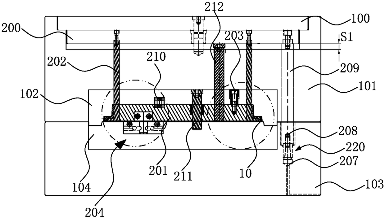
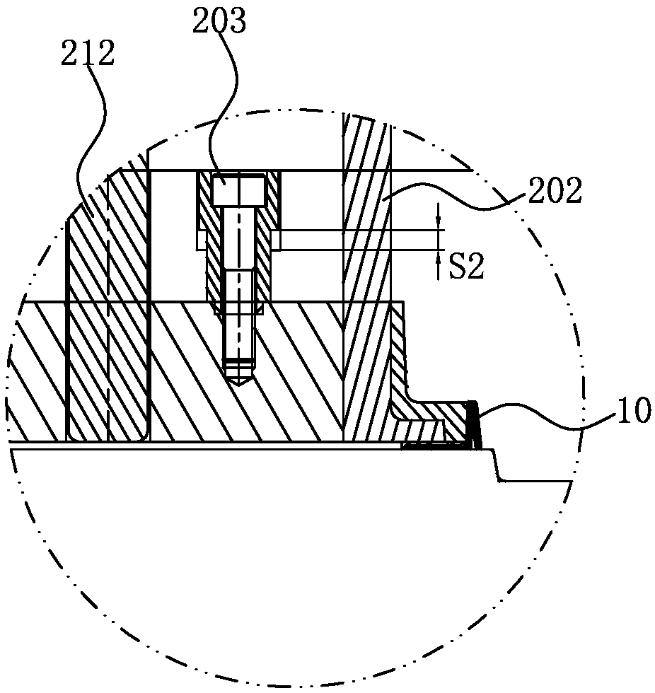
[0028] See Figure 2 to Figure 4 Shown, where figure 2 Draws a schematic diagram of the demolding structure of the present invention in a mold clamping state, image 3 Illustrated figure 2 A partial enlarged schematic diagram of Figure 4 Illustrated figure 2 Another partial enlarged schematic diagram of.

[0029] In a preferred embodiment, the demolding structure of the present invention is applied to a mold, and the mold includes an upper fixing plate 100, a female mold plate 101 under the upper fixing plate 100, a female mold core 102, a male mold plate 103, and a male mold plate. The mold core 104, the demolding structure includes:

[0030] The female mold ejector plate 200 is set in the female template 101, and a first movable stroke S1 is provided between the female mold ejector plate 200 and the female template 101, and the first movable stroke S1 may be 12 mm;

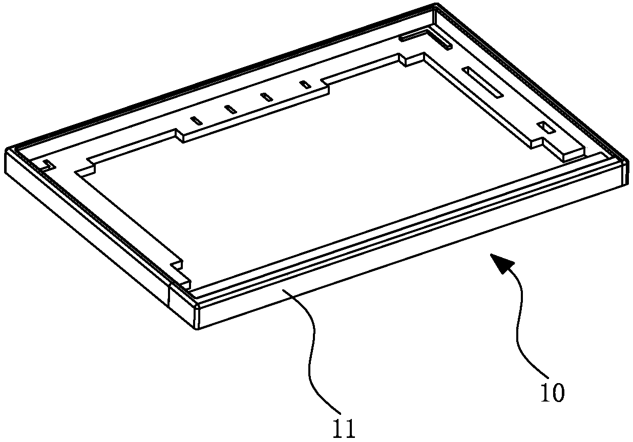
[0031] The elastic block 201 is set in the female mold core 102 and is set inside the product 10;

[0032] One e...


PUM


Abstract

A demoulding structure comprises a female mould centre plate, an elastic block, a female mould centre, a limiting piece, a mechanical on-off device, and a resin on-off device. A first activity strokeis arranged between the female mould centre plate and a female mould plate; the elastic block is arranged in a female mould core and arranged on the inner side of a product; one end of the female mould centre is fixed into the female mould centre plate, and the other end of the female mould centre abuts against the inner side of the product; one end of the limiting piece is fixed into the elasticblock, and a second activity stroke is arranged between the other end of the limiting piece and the female mould core; the mechanical on-off device is provided with a locking sleeve and a locking seat, the locking sleeve is fixed into a male mould core, one end of the locking seat is fixed into the elastic block, and the other end of the locking seat is locked in the locking sleeve; and the resinon-off device is provided with a nylon sleeve and a conical screw, the nylon sleeve is fixed into a male mould plate, and the conical screw is fixed to the female mould plate through a pulling rod. According to the demoulding structure, by arranging the structures such as the female mould centre plate, the female mould centre and the elastic block, staged jacking is conducted after a mould is opened, the problem that the product adheres to the female mould is solved, and the product appearance surface can be made into a high mirror surface.

Description

【Technical Field】 [0001] The invention relates to a mold structure, in particular to a demolding structure. 【Background technique】 [0002] In the production of plastic products, if the products are all molded on the side of the master mold, the product will stick to the master mold when the mold is opened. [0003] See figure 1 As shown, it shows a schematic diagram of a product. The product has a relatively high 10-circle circle, all molded on the side of the master mold, and the appearance surface 11 is a high mirror surface. Therefore, the product 10 will stick to the master mold when the mold is opened after molding, and the appearance surface 11 is not allowed to run off the slider during injection molding, and the high mirror surface cannot be polished. The product 10 cannot be injection molded. [0004] In view of this, it is really necessary to develop a demolding structure to solve the problem that the above-mentioned product 10 is molded on the master mold side and the ...

Claims


Application Information

Patent Timeline
IPC IPC(8): B29C45/40
CPCB29C45/4005
Inventor 郭雷
Owner SUZHOU MITAC PRECISION TECH
Why Eureka
Try Eureka