Ground and vehicle-mounted dual-purpose launcher tube missile erecting and parking device and launcher tube missile parking, transporting and erecting method thereof

A canister and ground technology, which is applied to the field of rapid erection of canisters, can solve the problems of large space occupation, tilting of canisters, inconvenience in use, etc., so as to shorten combat preparation time, save intermediate steps, and improve erection. The effect of efficiency

Active Publication Date: 2018-07-27
BEIJING XINLI MACHINERY
View PDF7 Cites 10 Cited by
  • Summary
  • Abstract
  • Description
  • Claims
  • Application Information

AI Technical Summary

Problems solved by technology

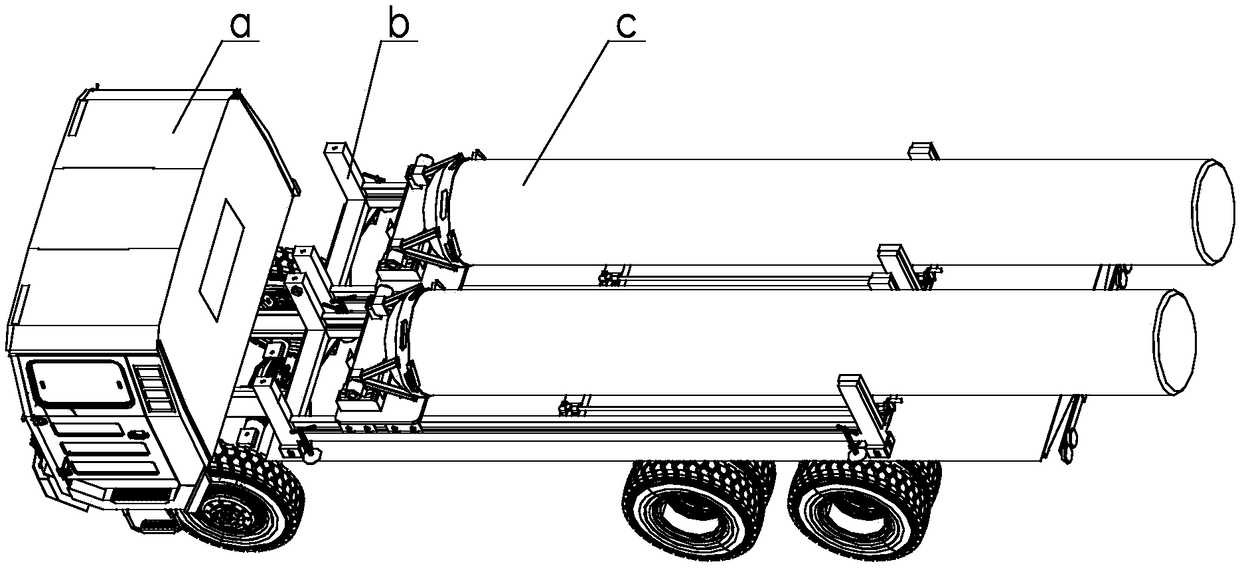
The existing parking rack only has the function of parking the cartridge c and cooperating with the vehicle a to transport the cartridge c; the existing erecting tool can only realize the function of erecting the cartridge on a flat ground and requires the assistance of multiple people when erecting
Especially in the actual use of a narrow space, it is necessary to hoist the barrel bullets on the vehicle from the parking frame to the erecting tooling by a crane and then use the crane to erect it. Low, and the barrel is prone to tilting when the ground is uneven, causing bumps

Method used


Image

  • Ground and vehicle-mounted dual-purpose launcher tube missile erecting and parking device and launcher tube missile parking, transporting and erecting method thereof
  • Ground and vehicle-mounted dual-purpose launcher tube missile erecting and parking device and launcher tube missile parking, transporting and erecting method thereof
  • Ground and vehicle-mounted dual-purpose launcher tube missile erecting and parking device and launcher tube missile parking, transporting and erecting method thereof

Examples


Embodiment Construction

[0049] The present invention will be further described below in conjunction with the accompanying drawings and specific embodiments. Examples of said embodiments are shown in the accompanying drawings, and the embodiments described with reference to the accompanying drawings are only exemplary and are only used for explaining the invention and not for limiting the invention.

[0050] The directions and positional relationships indicated by the terms "front", "rear", "left", "right", "inner", "outer" and so on described in the present invention are based on the pop-up and erection of the dual-purpose barrel mounted on the ground and on the vehicle. The direction and positional relationship of the parking device itself, and its components also inherit the direction and positional relationship, but this is only for the convenience of description and simplification of the description, and does not indicate or imply the specific orientation that the referred device or original parts...


PUM


Abstract

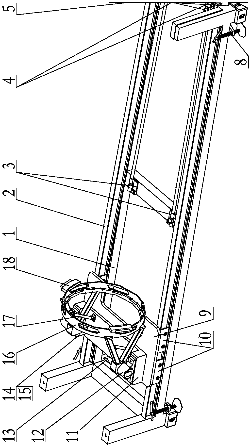
The invention discloses a ground and vehicle-mounted dual-purpose launcher tube missile erecting and parking device. The device is used for the parking, transporting along with a carrying vehicle anderecting of launcher tube missiles and comprises a frame body, sliding rails, three-degree-of-freedom sliding erecting mechanisms, missile foot locking mechanisms, parking supporting seats and carrying vehicle connecting seats, and the guiding rails are installed on the frame body; the three-degree-of-freedom sliding erecting mechanisms are arranged on the guiding rails and capable of sliding along the guiding rails, and the three-degree-of-freedom sliding erecting mechanisms are provided with launcher tube missile tail part locking mechanisms used for locking the tail parts of the launcher tube missiles; the parking supporting seats are arranged on the frame body and correspond to the missile foot positions of the launcher tube missiles respectively; the missile foot locking mechanisms are arranged on a front parking supporting seat and a rear parking supporting seat. The invention further discloses a launcher tube missile parking and erecting method of the device. The device has a direct erecting function, parking, transporting and erecting functions are integrated, the launcher tube missile can be rapidly, conveniently, safely and directly erected from the erecting parking device, middle procedures are eliminated, occupation space is reduced, and the device can adapt to complex ground environments.

Description

technical field [0001] The invention belongs to the field of military support equipment, and in particular relates to a structure capable of realizing the parking and quick erection of barrel bombs, especially a device capable of realizing quick erection of barrel bombs on a vehicle. Background technique [0002] Please refer to figure 1 As shown, at present, the parking, transportation and erection process of the cartridge c that needs to be transported horizontally and loaded vertically is realized by three different devices, namely, the parking frame, the vehicle a and the erecting tool. The existing parking frame only has the function of parking the cartridge c and cooperating with the vehicle a to transport the cartridge c; the existing erecting tool can only realize the function of erecting the cartridge on a flat ground and requires the assistance of multiple people when erecting. Especially in the actual use of a narrow space, it is necessary to hoist the barrel bul...

Claims


Application Information

Patent Timeline
Patent Type & Authority Applications(China)
IPC IPC(8): B60P3/40B60P7/08B60P7/16B60P7/15B60P1/12B60P1/30
CPCB60P1/12B60P1/30B60P3/40B60P7/0892B60P7/15B60P7/16
Inventor 王立勇刘霄亮杨希英马鹤坤高倩
Owner BEIJING XINLI MACHINERY
Why Eureka
Try Eureka