

Screw feeding device directly driven by frameless combination type permanent magnet synchronous linear motor
A permanent magnet synchronous linear and screw feeding technology, applied in the field of machinery, can solve the problems of continuous speed regulation, affecting the use of motors, poor geological adaptability, etc., and achieve the effect of flexible selection, energy output, and large energy output
- Summary
- Abstract
- Description
- Claims
- Application Information
AI Technical Summary
Problems solved by technology
Method used
Image

Examples
Embodiment 1
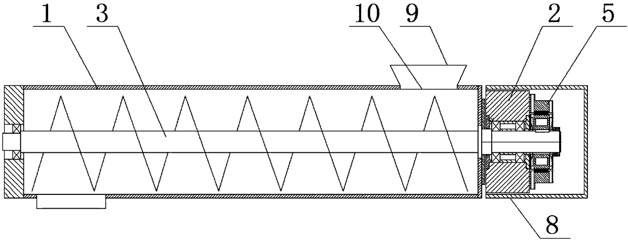
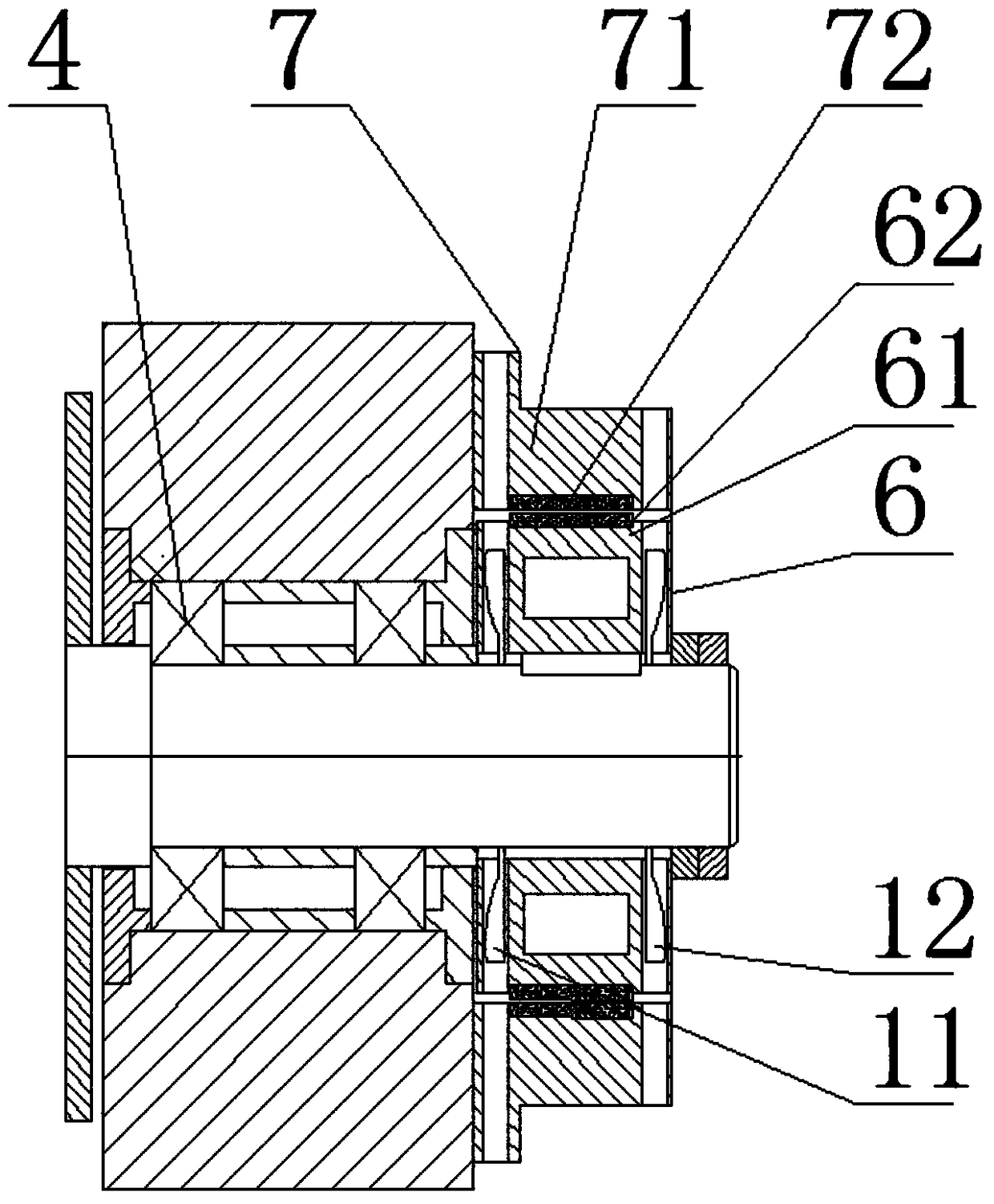
[0034] like figure 1 , 2 As shown, this embodiment provides a screw feeding device directly driven by a frameless combined permanent magnet synchronous linear motor, including a frame 2, a feeding chamber 1 installed on the frame 2, a screw shaft 3, a bearing 4, The helical blade and the frameless combined permanent magnet synchronous linear motor 5 installed on the screw shaft 3, the screw shaft 3 runs through the feeding chamber 1, and is installed on the frame 2 through the bearing 4, so that The screw shaft 3 is rotationally connected with the feeding chamber 1; the screw shaft 3 is directly driven by the frameless combined permanent magnet synchronous linear motor 5; the frameless combined permanent magnet synchronous linear motor 5 includes a stator assembly 7 and the rotor assembly 6; the stator assembly 7 is fixedly installed on the frame 2 to provide a rotating magnetic field for the rotor assembly 6; the rotor assembly 6 having permanent magnet properties is fixedly...
Embodiment 2
[0039] like Figure 4 As shown, this embodiment provides a screw feeding device directly driven by a frameless combined permanent magnet synchronous linear motor. Compared with Embodiment 1, the difference is that the stator assembly 7 is a non-circular structure, so The stator assembly 7 is composed of six sets of stator units 73 in a fan-shaped disc structure; the stator unit 2 73 is an independent control mechanism; the stator unit 73 includes a stator core and is wound on the stator iron The stator winding on the core; the feeding chamber 1 includes a feeding port 9 and a screen 10 located in the feeding port 9 .
[0040] As a preference of this embodiment, the rotor assembly 6 includes a rotor base 61 and a disc-shaped magnetic steel base plate 63, the rotor base 61 is fixedly mounted on the screw shaft 3, and the disc-shaped magnetic steel base plate 2 63 are evenly distributed on the rotor base 61 around the center line of the screw shaft 3; the end of the screw shaft ...
Embodiment 3
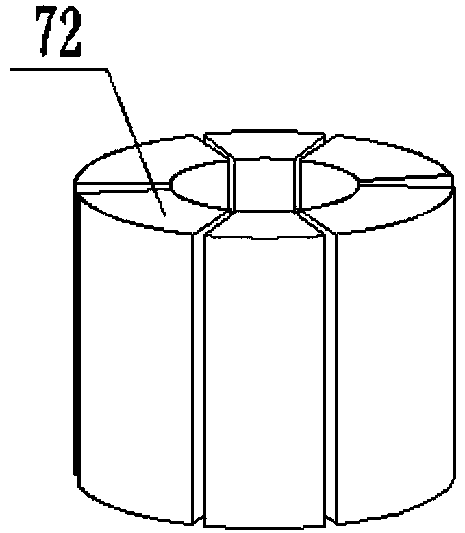
[0043] like Figure 5 As shown, this embodiment provides a screw feeding device directly driven by a frameless combined permanent magnet synchronous linear motor. Compared with Embodiment 1, the difference is that the stator assembly 7 is a non-circular structure , the stator assembly 7 is composed of six sets of stator unit one 72 in a fan-shaped arc-shaped structure and six sets of stator unit two 73 in a fan-shaped disc structure; the first stator unit 72 and the second stator unit 73 are independently controlled Mechanism: The first stator unit 72 and the second stator unit 73 each include a stator core and a stator winding wound on the stator core.
[0044] As a preference of this embodiment, the rotor assembly 6 includes a rotor base 61, an arc-shaped magnetic steel base plate 1 62 and a disk-shaped magnetic steel base plate 2 63, the rotor base 61 is fixedly mounted on the screw shaft 3, The arc-shaped magnetic steel base plate 1 62 and the disk-shaped magnetic steel b...
PUM
 Abstract
Description
Claims
Application Information