Flange pushing mechanism and flange machining line with same

A technology of pushing mechanism and flange, which is applied to conveyors, conveyor objects, conveyor control devices, etc., can solve the problem of inability to realize automatic flange pushing and other problems.

Inactive Publication Date: 2018-07-31
ZHUHAI GREE INTELLIGENT EQUIP CO LTD +1
View PDF0 Cites 2 Cited by
  • Summary
  • Abstract
  • Description
  • Claims
  • Application Information

AI Technical Summary

Problems solved by technology

[0004] The main purpose of the present invention is to provide a flange pushing mechanism and a flange processing line with it, so as to solve the problem that the flange processing line in the prior art cannot realize the automatic pushing of flanges

Method used


Image

  • Flange pushing mechanism and flange machining line with same
  • Flange pushing mechanism and flange machining line with same

Examples


Embodiment Construction

[0022] It should be noted that, in the case of no conflict, the embodiments in the present application and the features in the embodiments can be combined with each other. The present invention will be described in detail below with reference to the accompanying drawings and examples.

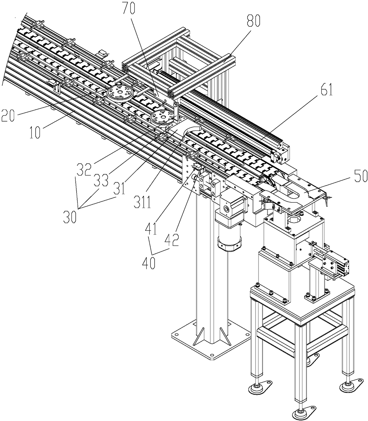
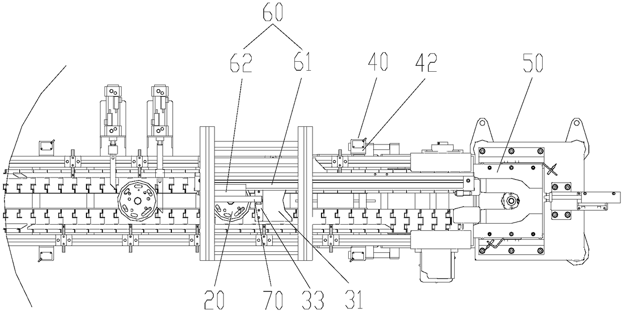
[0023] The present invention provides a flange pushing mechanism, please refer to figure 1 with figure 2 , the flange pushing mechanism is used to push the flange parts 20 on the flange conveying line 10 onto the support table 50, including: a pushing part 30, the pushing part 30 is arranged above the flange conveying line 10, and the pushing part The part 30 is movably arranged along the conveying direction of the flange conveying line 10, so as to move the flange part 20 between the pushing part 30 and the supporting platform 50 onto the supporting platform 50; wherein, the pushing part 30 is vertically The direction position is adjustable so that the flange part 20 located upstream of the...


PUM


Abstract

The invention provides a flange pushing mechanism and a flange machining line with the same. The flange pushing mechanism is used for pushing flange components on a flange conveying line to a supporting table, and comprises a pushing portion, the pushing portion is arranged above the flange conveying line and movable in the conveying direction of the flange conveying line so as to make the flangecomponents between the pushing portion and a supporting table move to the supporting table, and the pushing portion is adjustable in position in the vertical direction so that the flange components onthe upstream of the pushing portion can pass through the bottom of the pushing portion. The flange pushing mechanism solves the problem that a flange machining line cannot achieve automatic pushing of flanges in the prior art.

Description

technical field [0001] The invention relates to the field of mechanical processing, in particular to a flange pushing mechanism and a flange processing line with the same. Background technique [0002] During the flange processing process, the flange needs to be transported to the flange processing station through the assembly line. [0003] However, in the prior art, it is impossible to realize the automation of sending the flange from the assembly line to the processing station or testing station, thereby reducing the processing efficiency. Contents of the invention [0004] The main purpose of the present invention is to provide a flange pushing mechanism and a flange processing line with it, so as to solve the problem that the flange processing line in the prior art cannot realize automatic flange pushing. [0005] In order to achieve the above object, according to one aspect of the present invention, a flange pushing mechanism is provided, which is used to push the f...

Claims


Application Information

Patent Timeline
Patent Type & Authority Applications(China)
IPC IPC(8): B65G47/82B65G47/74B65G43/08
CPCB65G47/82B65G43/08B65G47/74B65G2201/0214B65G2203/0233B65G2203/042
Inventor 吴礼剑何健樟宋家涛
Owner ZHUHAI GREE INTELLIGENT EQUIP CO LTD
Why Eureka
Try Eureka