A fast welding device for a new energy lithium battery pack

A lithium battery pack, fast welding technology, applied in welding equipment, resistance welding equipment, welding/welding/cutting items, etc., can solve the time-consuming and labor-intensive problems, achieve the effect of improving work efficiency and realizing automatic feeding and transferring materials

Active Publication Date: 2021-09-03
汇通胜(广州)科技有限公司
View PDF1 Cites 0 Cited by
  • Summary
  • Abstract
  • Description
  • Claims
  • Application Information

AI Technical Summary

Problems solved by technology

[0005] In order to overcome the time-consuming and labor-intensive shortcomings of the existing equipment, the technical problem is to provide a fast welding device for new energy lithium battery packs that can automatically load and weld, saving time and effort

Method used


Image

  • A fast welding device for a new energy lithium battery pack
  • A fast welding device for a new energy lithium battery pack
  • A fast welding device for a new energy lithium battery pack

Examples


Embodiment 1

[0065] A fast welding device for a new energy lithium battery pack, such as figure 1 As shown, it includes a base 1, a mounting plate 2, an electric welding mechanism 3 and a pushing mechanism 4, the left side of the base 1 is provided with a mounting plate 2, the left side of the base 1 is provided with an electric welding mechanism 3, and the right side of the base 1 is provided with a pushing mechanism 4.

[0066] When people need to weld the battery, the battery is first placed on the mounting plate 2, and then the pushing mechanism 4 is controlled so that the parts of the pushing mechanism 4 move the battery to the left, and then the iron sheet is placed between the tops of the batteries. Then start the parts of the electric welding mechanism 3, and press the parts of the electric welding mechanism 3 to move down, so that the parts of the piezoelectric welding mechanism 3 weld the battery. After completion, control the pushing mechanism 4, so that the parts of the pushing...

Embodiment 2

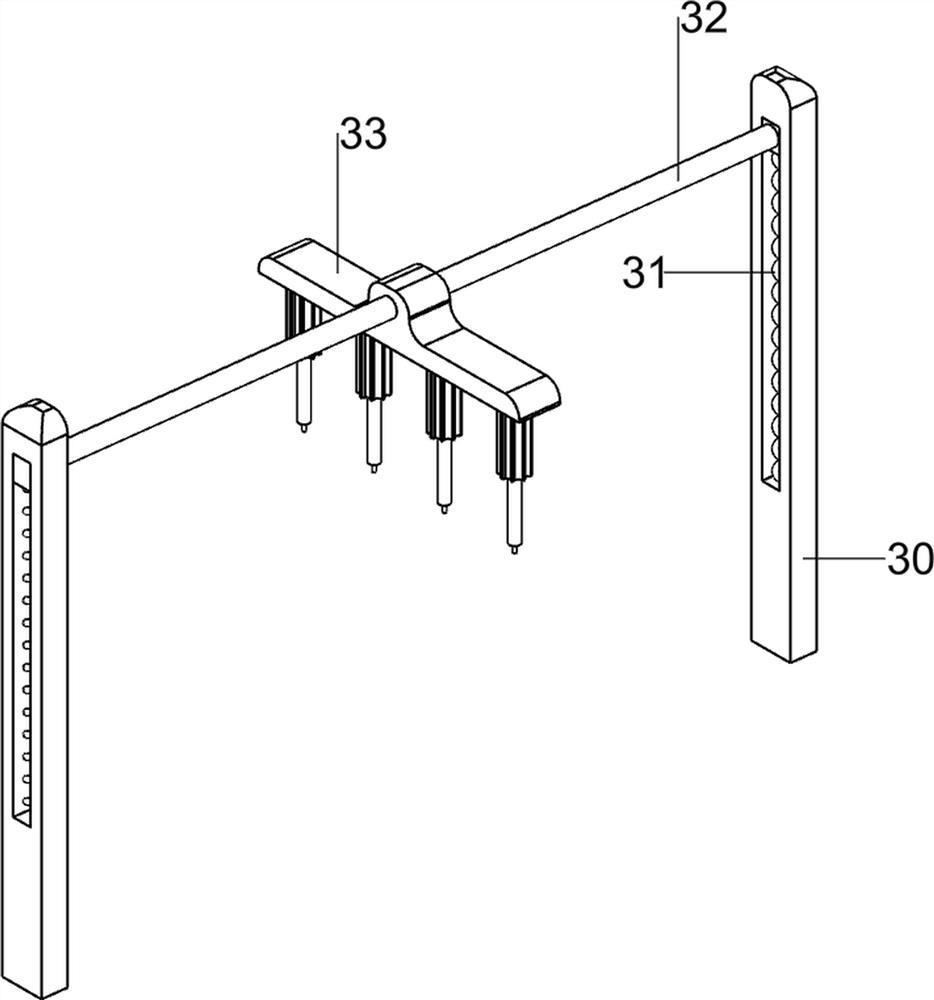
[0068] On the basis of Example 1, such as Figure 2-4 As shown, the electric welding mechanism 3 includes a first slide rail 30, a first spring 31, a lifting rod 32 and a spot welder 33, and the front and rear sides of the left part of the base 1 are connected with the first slide rail 30, between the first slide rail 30 There is a lifting rod 32 slidingly connected between them, and a first spring 31 is connected between the front and rear sides of the bottom of the lifting rod 32 and the inner bottom wall of the first slide rail 30 , and a spot welder 33 is arranged in the middle of the lifting rod 32 .

[0069]When people need to weld the battery, start the spot welder 33, press the lifting lever 32, drive the spot welder 33 to move down and weld the battery, the first spring 31 is compressed, let go after completion, and the first spring 31 Under the action, drive the lifting rod 32 and the spot welder 33 to move upwards and reset, and close the spot welder 33 to get final...

Embodiment 3

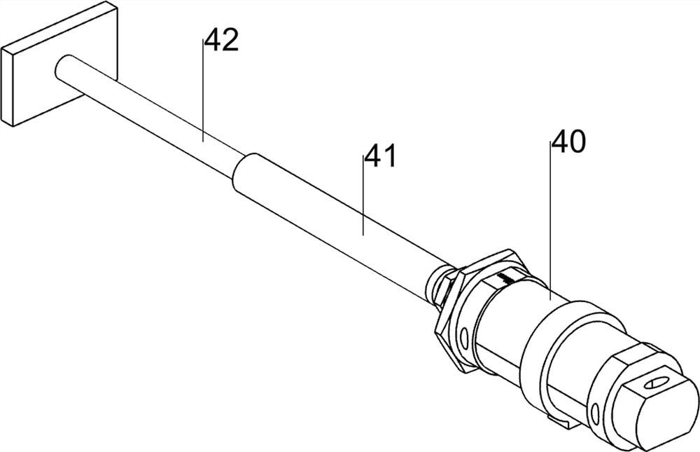
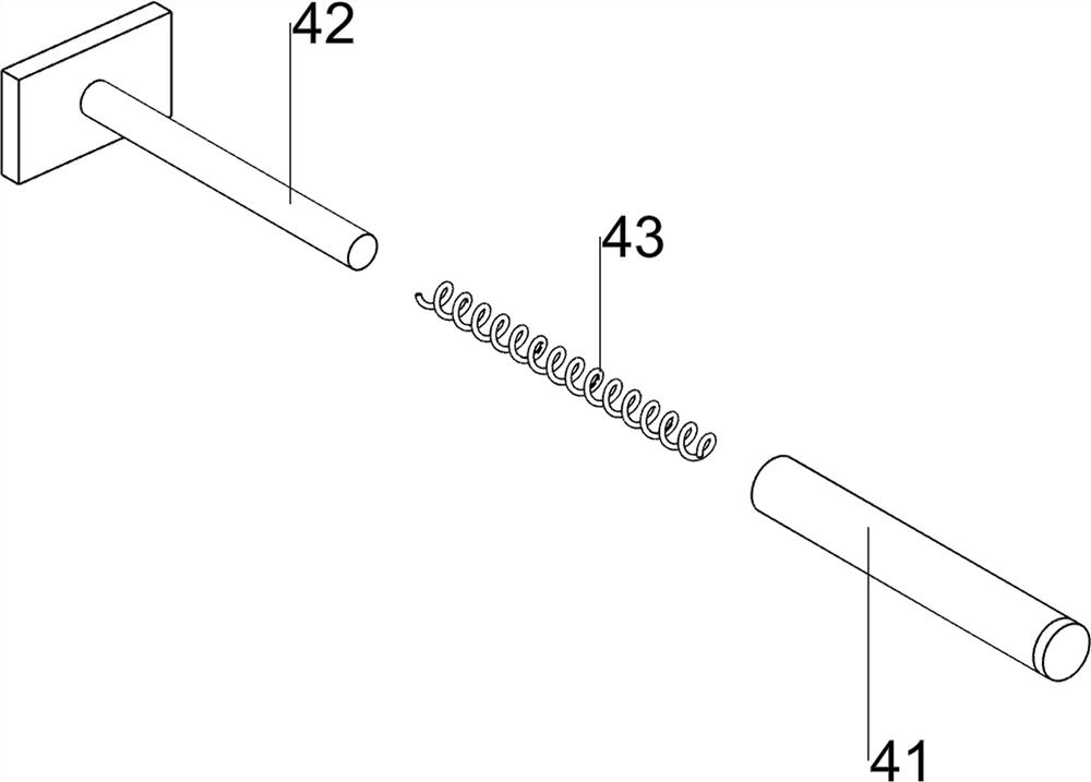
[0073] On the basis of Example 2, such as Figure 5-9 As shown, a limit mechanism 5 is also included, and the limit mechanism 5 includes a first connecting rod 50, an extrusion block 51, a limiter 52, a wedge block 53, a mounting block 54, a first fixed rod 55 and a third spring 56 , the front and rear sides of the hollow cylinder 41 are connected with first connecting rods 50, the first connecting rods 50 are provided with extruding blocks 51, and the left and right sides of the base 1 are connected with mounting blocks 54, and the mounting blocks 54 are all slidably connected. There is a first fixed rod 55, the inside of the first fixed rod 55 is provided with a stopper 52, the stopper 52 is slidably connected with the mounting plate 2, and the right side of the stopper 52 is provided with a wedge block 53, and the first fixed rod 55 A third spring 56 is provided between the outer side and the mounting block 54 on the same side, and the third spring 56 is sleeved on the oute...


PUM


Abstract

The invention relates to a welding device, in particular to a rapid welding device for a new energy lithium battery pack. The technical problem is: to provide a fast welding device for a new energy lithium battery pack that can automatically load and weld, and save time and effort. A rapid welding device for such a new energy lithium battery pack is provided, including a base and a mounting plate, the mounting plate is provided on one side of the base; an electric welding mechanism is provided on one side of the base; a pushing mechanism is provided on one side of the base Pushing mechanism. Through the cooperation between the electric welding mechanism and the pushing mechanism, the effect of automatic pushing and welding of the battery can be realized, which can improve people's work efficiency. Through the cooperation between the limit mechanism and the lifting mechanism, when the battery is welded, The battery can be positioned and clamped, and the welding can be performed automatically without manual operation.

Description

technical field [0001] The invention relates to a welding device, in particular to a rapid welding device for a new energy lithium battery pack. Background technique [0002] Since the positive and negative poles (ie, both sides) of the battery pack need to be welded, current welding machines usually use single-station type left and right welding heads to perform back-step resistance welding at the same time. However, it is all welded manually by hand now. [0003] Patent application CN201921938237.9 A battery pack welding device, the battery pack welding device includes a laser welder, a driving device, a pressure plate, a limit block, a base, a bottom plate, a support plate, an elastic device, and a guide post; the guide post is set On the support plate, the bottom plate is provided with a guide hole, the guide post passes through the guide hole, and the bottom plate can move up and down along the guide post; the elastic device is sleeved on the guide post and located be...

Claims


Application Information

Patent Timeline
Patent Type & Authority Patents(China)
IPC IPC(8): B23K11/11B23K11/36B23K101/36
CPCB23K11/11B23K11/36B23K2101/36
Inventor 刘铭英
Owner 汇通胜(广州)科技有限公司
Why Eureka
Try Eureka