Metal window welding clamp device

A fixture device and welder technology, applied in metal processing equipment, auxiliary devices, manufacturing tools, etc., can solve problems such as poor welding quality, and achieve the effect of increasing the contact area of ​​pressing

Pending Publication Date: 2022-01-07
WUXI DONGZHOU MARINE EQUIP CO LTD
View PDF0 Cites 0 Cited by
  • Summary
  • Abstract
  • Description
  • Claims
  • Application Information

AI Technical Summary

Problems solved by technology

[0005] The object of the present invention is to provide metal window welder clamping device, to solve the problem of poor welding quality proposed in the above-mentioned background technology

Method used


Image

  • Metal window welding clamp device
  • Metal window welding clamp device
  • Metal window welding clamp device

Examples


Embodiment 1

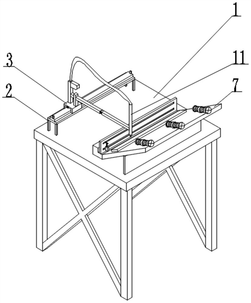
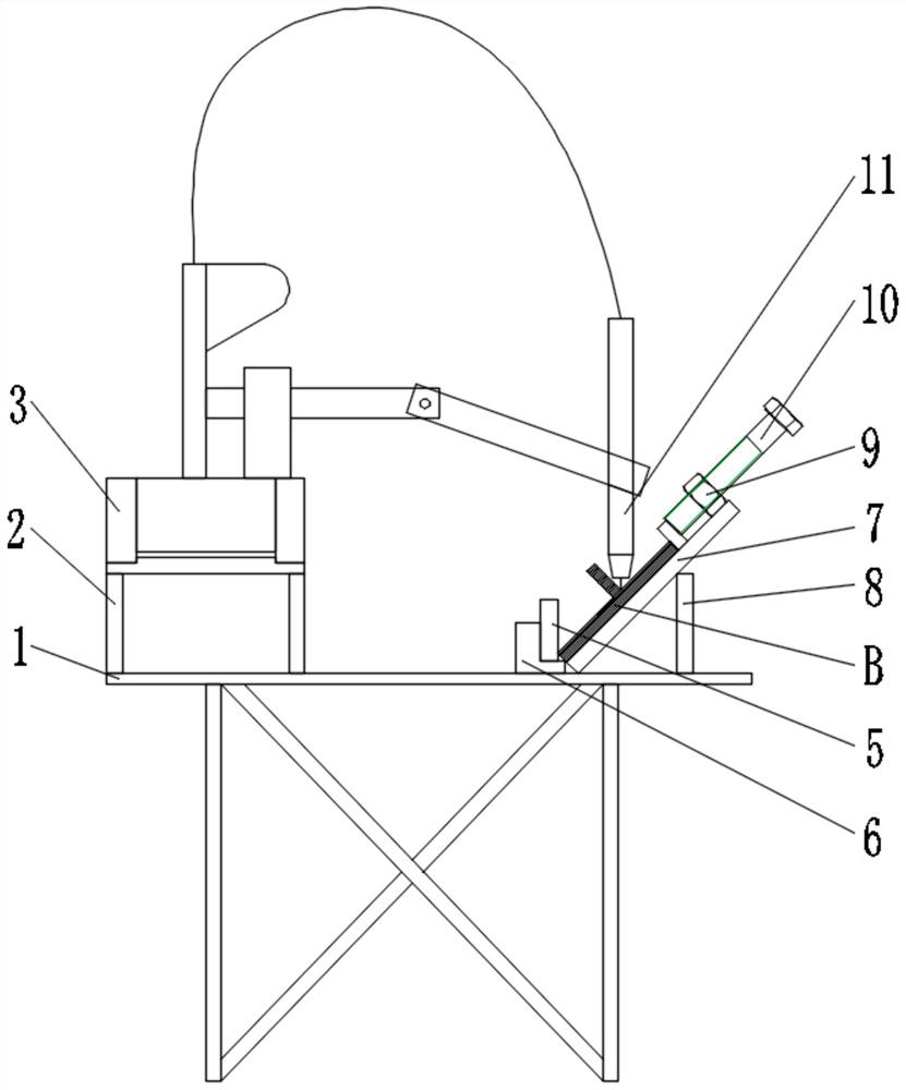
[0024] Example 1: See figure 1 and figure 2 , metal window welder fixture device, including welding base 1, welding trolley 3, welding positioning frame and pressing assembly, it is characterized in that: welding positioning frame is welded on welding base 1, and welding positioning frame includes a supporting base 7 that is arranged obliquely, The front end of the support seat 7 is fixed with the front positioning block 5, and the rear end of the support seat 7 is fixed to press the assembly; the window seat B for welding is placed on the support seat 7, the front end of the window seat B contacts the front positioning block 5, and the rear end of the window seat B The end is compressed by the pressing assembly; the walking guide rail 2 is fixed on the welding base 1, and the traveling guide rail 2 is arranged in parallel with the support seat 7, and the welding trolley 3 is slidably connected to the traveling guide rail 2, and the front end of the welding trolley 3 is conne...

Embodiment 2

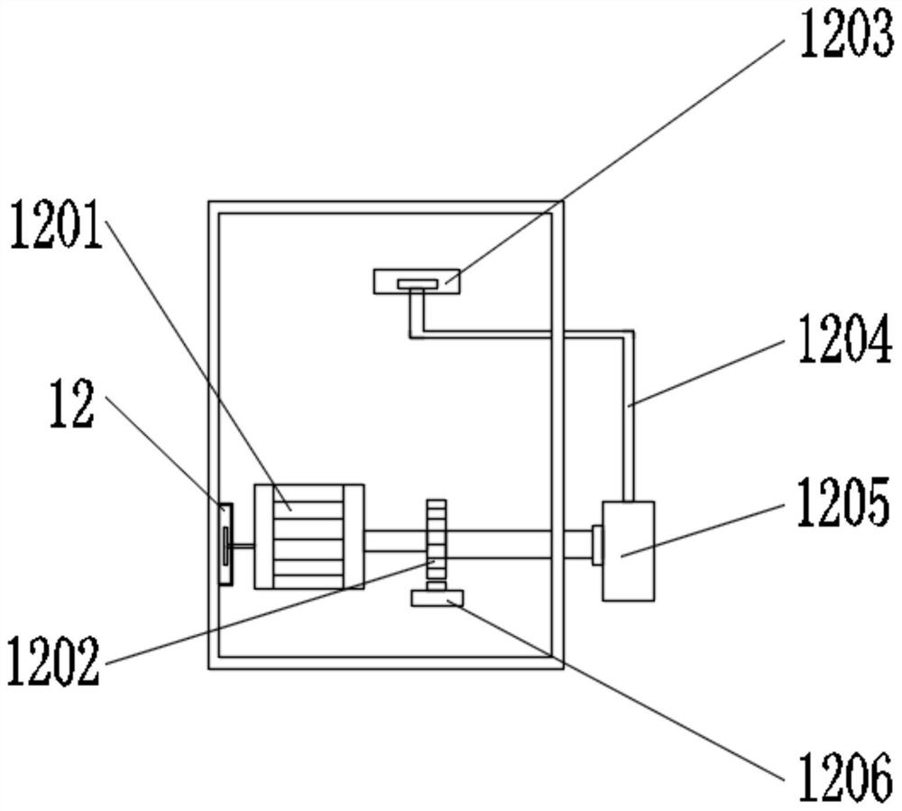
[0025] Example 2: see image 3 and Figure 4 , the inner wall of the first slideway 12 is equipped with a first pulley, one end of the first pulley is installed with a first pillar, one end of the first pillar is installed with a first motor 1201, and the output end of the first motor 1201 is installed with a rotating rod. The outer wall of the bar is equipped with a first gear 1202, and one end of the rotating bar is equipped with a push block 1205 through a bearing. The top of 1205 is equipped with bracket 1204, and one end of bracket 1204 is equipped with second pulley, and the outer wall of second pulley is connected with the inner wall of second slideway 1203, and the bottom of welding trolley 3 is equipped with second pole 1302, and the second support One end of the bar 1302 is equipped with a second motor 1303, and the output end of the second motor 1303 is equipped with a second gear 1301, and the second gear 1301 is engaged with the second gear rod 13, and the rotati...


PUM


Abstract

The invention discloses a metal window welding clamp device which comprises a welding base, a welding trolley, a welding positioning frame and a pressing assembly. The welding positioning frame is welded to the welding base and comprises a supporting seat arranged obliquely, a front positioning block is fixedly arranged at the front end of the supporting seat, and the pressing assembly is fixed to the rear end of the supporting seat. a window base to be welded is placed on the supporting seat, and the front end of the window base makes contact with the front positioning block. By installing the welding trolley, a locking nut and a second motor, automatic clearing of welding slag, automatic moving of the welding trolley and the welding effect on the window base and a glass blocking frame are achieved, the welding trolley can drive a welding nozzle to walk along a walking guide rail, and therefore the function of welding the window base and the glass blocking frame is achieved. A support moves to drive a second pulley to move, a second gear rotates to drive the welding trolley to move, and the functions of automatic clearing of the welding slag, automatic moving of the welding trolley and welding of the window base and the glass blocking frame are achieved.

Description

technical field [0001] The invention relates to the technical field of ship metal window processing equipment, in particular to a clamp device for a metal window welder. Background technique [0002] With the development of the ship industry, customers have higher and higher requirements for ship outfitting equipment. In the existing technology, the window seat and the glass frame are generally welded and connected separately, and then bent into a round shape, and finally welded together As a whole, the traditional welding process not only has low production efficiency, but also has poor welding quality, which affects the aesthetics of the product. [0003] The defective that existing metal window welder fixture device exists is: [0004] 1. The existing metal window welding fixture device not only has low production efficiency, but also has poor welding quality, which affects the aesthetics of the product. Contents of the invention [0005] The object of the present inv...

Claims


Application Information

Patent Timeline
IPC IPC(8): B23K37/00B23K37/02B23K37/04
CPCB23K37/00B23K37/0247B23K37/0461B23K37/0443
Inventor 宋勇荣惠海平
Owner WUXI DONGZHOU MARINE EQUIP CO LTD
Why Eureka
Try Eureka