Engine camshaft assembly and motorcycle

A camshaft and engine technology, applied to engine components, machines/engines, mechanical equipment, etc., can solve problems such as decompression body fatigue fracture, large rotational inertia force and impact load, increase maintenance frequency, etc., and reduce manufacturing difficulty Small size, improved load-bearing capacity, and flexible movement

Inactive Publication Date: 2011-10-26
CHONGQING LONCIN MOTOR
View PDF4 Cites 3 Cited by
  • Summary
  • Abstract
  • Description
  • Claims
  • Application Information

AI Technical Summary

Problems solved by technology

However, when the engine rotates at high speed or the rotation speed is changed, this structure produces a large rotational inertial force and impact load, which causes fatigue fracture of the decompression body and increases the frequency of maintenance.

Method used


Image

  • Engine camshaft assembly and motorcycle
  • Engine camshaft assembly and motorcycle
  • Engine camshaft assembly and motorcycle

Examples


Embodiment Construction

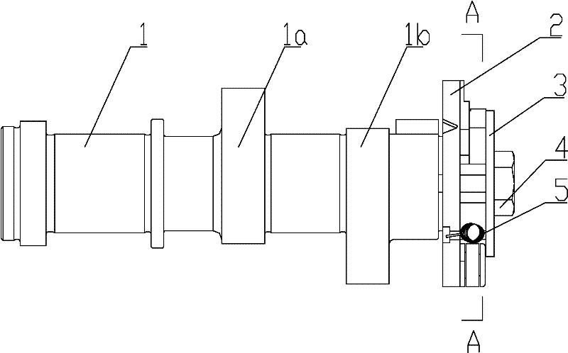
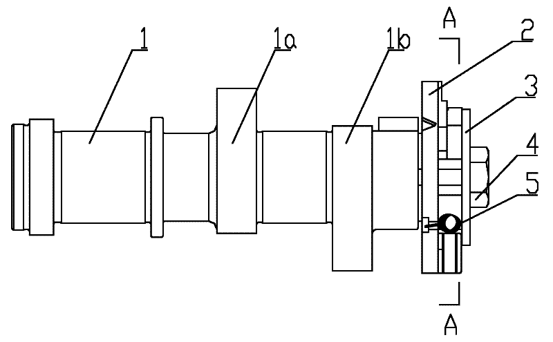
[0019] figure 1 It is a structural schematic diagram of the present invention, figure 2 based on figure 1 A sectional view along A-A, as shown in the figure: the engine camshaft assembly of this embodiment includes a camshaft 1 and a pressure reducing valve assembly, and the camshaft 1 is provided with an intake cam 1a and an exhaust cam 1b, the The pressure reducing valve assembly includes a pressure reducing valve body 2, a centrifugal block 6 and a fastening bolt 4, the pressure reducing valve body 2 is concentrically fixedly fitted with the camshaft 1 in the circumferential direction, and the fastening bolt 4 is threaded and screwed on the camshaft 1 and fasten the relief valve body 2 axially to the camshaft 1;

[0020] The camshaft 1 is provided with a shoulder that limits the position of the pressure reducing valve body, and the pressure reducing valve body 2 is provided with a central hole and is overlaid on the camshaft 1 through the central hole, and then pressed a...


PUM


Abstract

The invention relates to an engine camshaft assembly and a motorcycle. The assembly comprises a camshaft and a pressure relief assembly; a timing component and the pressure relief assembly are respectively positioned at two ends of the camshaft; the pressure relief assembly comprises a pressure relief valve body, a centrifugal block and a fastening bolt. The engine camshaft assembly provided by the invention has the following advantages: the pressure relief valve body is pressed tightly and fixed through a bolt, a compression base plate, a flange on the pressure relief valve body and a shaft shoulder on the camshaft, the compression contact area of the flange can be increased, the reliability of fastening is ensured, the axial degree of freedom of the pressure relief valve body is restricted, and simultaneously the circumferential degree of freedom of the pressure relief valve body also can be limited to a certain extent; by virtue of the circumferential direction limit structure of the pressure relief valve body, the operation reliability of the pressure relief assembly is ensured; the mounting structure has high integration, the positioning effect is also good, and the mounting errors can be avoided better; and simultaneously the pressure relief valve body can bear, transmit and counteract the rotary inertia force and impact loading generated by the high-speed rotation of an engine, the fatigue and crack phenomena do not occur, and the service life is ensured.

Description

technical field [0001] The invention relates to an auxiliary component for an engine, in particular to a camshaft component for switching engine valves and a motorcycle thereof. Background technique [0002] The engine camshaft assembly is a more important part of the valve train, including the camshaft and the intake and exhaust cams, timing components and pressure relief valve components set on the camshaft. The pressure reducing valve assembly is mainly used to reduce the pressure in the engine cylinder when starting, reduce the external force of starting, and avoid the phenomenon that the load of the starting motor is too high or the manual handle rebounds vigorously. [0003] The commonly used pressure reducing valve assembly generally adopts a centrifugal block structure, and the centrifugal block is set in a way that can move along the radial plane of the camshaft. When the engine is not started, the pressure reducing valve stem connected with the centrifugal fast mak...

Claims


Application Information

Patent Timeline
Patent Type & Authority Applications(China)
IPC IPC(8): F01L1/047F01L13/08
Inventor 杜执飞廖朝斌焦胜林陈艺方陈士杰林峰彭发碧
Owner CHONGQING LONCIN MOTOR
Why Eureka
Try Eureka