Locking ring for release bearing

A technology for separating bearings and locking rings, applied in the field of locking rings, which can solve the problems affecting the service life of sliding sleeve bearing shells and wear of chute sliders, and achieve simple structure, reduced friction surface, and reduced friction loss Effect

Pending Publication Date: 2017-08-04
福缔汽车(太仓)有限公司
View PDF8 Cites 2 Cited by
  • Summary
  • Abstract
  • Description
  • Claims
  • Application Information

AI Technical Summary

Problems solved by technology

However, due to the large sliding contact surface and close contact of this sliding block chute combination method, it is very easy to cause wear on the sliding groove and the sliding block itself, which seriously affects the service life of the sliding sleeve and the bearing housing.

Method used


Image

  • Locking ring for release bearing
  • Locking ring for release bearing
  • Locking ring for release bearing

Examples


Embodiment Construction

[0025] In order to make the object, technical solution and advantages of the present invention clearer, the present invention will be further described in detail below in conjunction with the embodiments. It should be understood that the specific embodiments described here are only used to explain the present invention, not to limit the present invention.

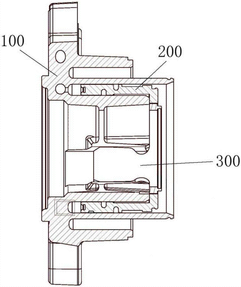
[0026] figure 1 A release bearing using the locking ring 300 of the present invention is shown. When the release bearing works, the sliding sleeve 200 moves axially relative to the bearing shell 100, and the locking ring 300 is fixed between the two to prevent relative radial rotation. Wherein, the sliding sleeve 200 is provided with a locking groove for fixing the locking ring 300 , and the bearing housing 100 is also provided with an axially extending locking groove for fixing the locking ring 300 .

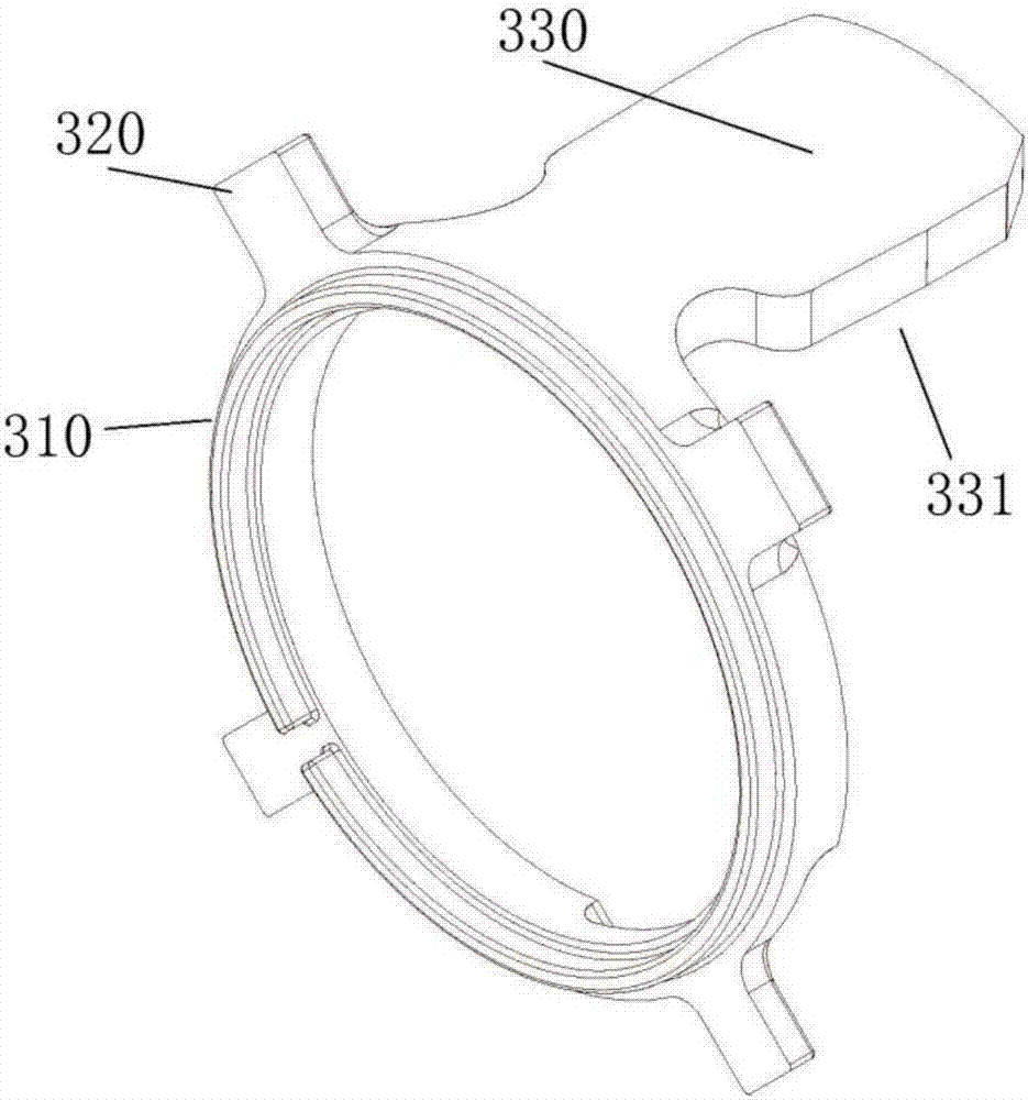
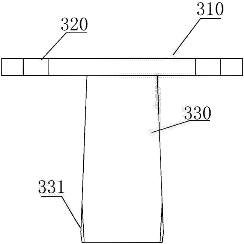
[0027] figure 2 and image 3 They are a perspective view and a side view, respectively, of a locking ring 300 accordi...


PUM


Abstract

The invention provides a locking ring for a release bearing. The locking ring comprises a ring-shaped connecting ring, a clamping lug and a lock tongue, wherein the clamping lug extends outwards along the radial direction of the outer edge of the connecting ring, and the lock tongue is vertical to the plane with the connecting ring and axially extends; the clamping lug is clamped into a corresponding clamping groove of a sliding sleeve of the release bearing, and the lock tongue is inserted into a corresponding lock groove in a shell of the release bearing. The locking ring has the advantages of simple structure and convenient processing and can further increase the lubrication level and reduce frictional loss on the basis of effectively avoiding radially rotating among the parts of the release bearing, and thus the service life of the release bearing is prolonged.

Description

technical field [0001] The invention relates to the field of automobile bearings, in particular to a locking ring for a clutch release bearing. Background technique [0002] The clutch release bearing is usually installed between the clutch and the transmission, which facilitates the axial movement of the release lever along the output shaft of the clutch while rotating, thus ensuring the smooth engagement of the clutch, soft separation, reducing wear and extending the use of the clutch and the entire transmission system life. However, during the working process of the release bearing, due to the frequent reciprocating movement of the sliding sleeve in the axial direction, it is very likely that the radial relative rotation will occur due to looseness, and this radial rotation will make the sealing ring bear radial force. Shear stress, over time, can damage the seal, leading to seal failure. [0003] In the prior art, in order to avoid relative rotation between the sliding...

Claims


Application Information

Patent Timeline
Patent Type & Authority Applications(China)
IPC IPC(8): F16D23/14F16C33/02
CPCF16C33/02F16D23/14F16C2361/43
Inventor 唐春燕吴强郝干成陶健
Owner 福缔汽车(太仓)有限公司
Why Eureka
Try Eureka