Automatic fin feeding device of fin evaporator

A finned evaporator, automatic technology, applied in the direction of feeding device, positioning device, storage device, etc., can solve the problems of wrong direction of fins, poor pipe penetration, low work efficiency, etc.

Pending Publication Date: 2019-12-03
HEFEI TAITONG REFRIGERATION TECH CO LTD
View PDF0 Cites 0 Cited by
  • Summary
  • Abstract
  • Description
  • Claims
  • Application Information

AI Technical Summary

Problems solved by technology

Each auxetic production line needs 5 people to operate, of which 4 people arrange the fins, and 1 person wears the pipe. The number of people employed is large, the labor intensity is high, and the work efficiency is low. Since the fins are currently arranged mainly by hand, the quality of the fins is caused. There is no guarantee, there will be various phenomena such as missing row, wrong row, wrong direction of fins, etc., resulting in poor tube penetration and affecting production efficiency
Also, because the fins are thinner and sharper metal, workers must wear multiple pairs of rubber gloves when operating. Even so, there is still a risk of workers scratching their hands, which is prone to work-related accidents

Method used


Image

  • Automatic fin feeding device of fin evaporator
  • Automatic fin feeding device of fin evaporator
  • Automatic fin feeding device of fin evaporator

Examples


Embodiment Construction

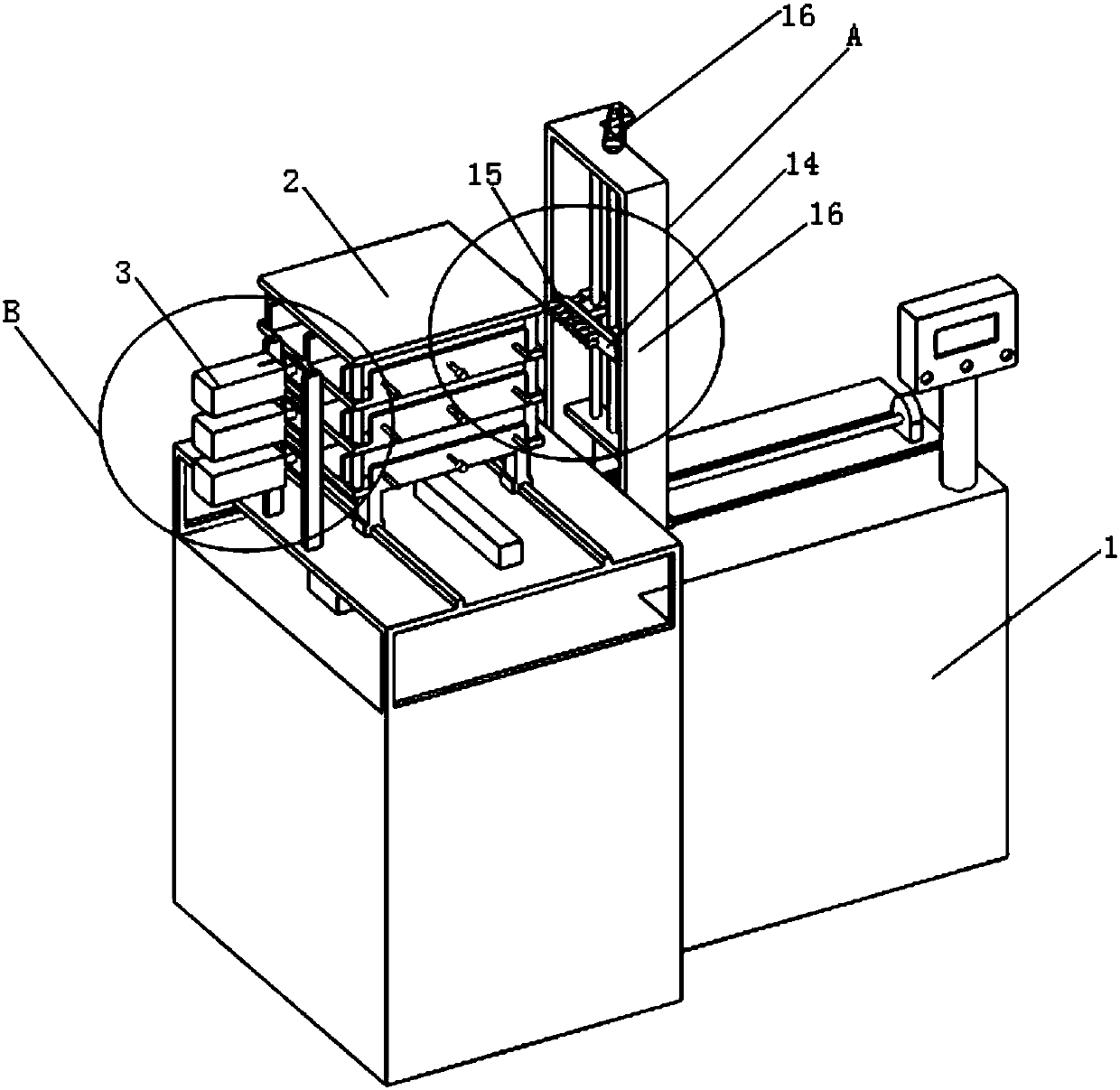
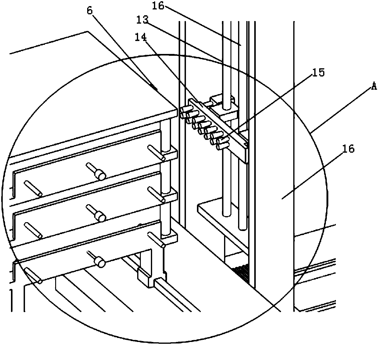
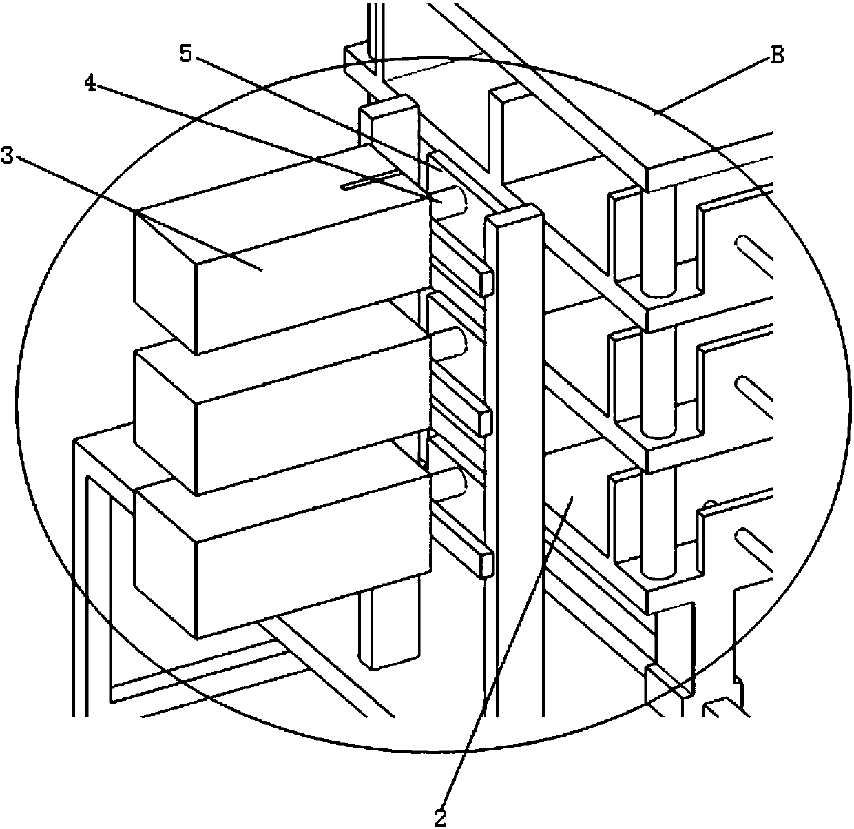
[0012] See attached Figure 1-4 As shown, a finned evaporator automatic loading device includes a frame 1 and a storage box 2 arranged on the frame 1, and a cylinder 3 is arranged on the rear side of the storage box 2, and the cylinder 3 is connected to the push rod 4, and a push plate 5 is arranged on the push rod 4, and the push plate 5 is arranged in the material storage box 2, and a fin limit bar is provided on the front side of the material storage box 2 6. A first linear guide rail 7 and a second linear guide rail 8 are arranged on the frame 1 on the lower side of the storage box 2, and a chip arrangement mold 9 is arranged on the first linear guide rail 7. On the second linear guide rail 8 is a sheet arranging limiting plate 10, connected with the sheet arranging mold 9 is a first screw motor 11, and connected with the sheet arranging limiting plate 10 is a second screw motor 12 The inserting device is installed on the side of material storage box 2, and it comprises t...


PUM


Abstract

The invention relates to the field of fin evaporator production equipment, more specifically, relates to an automatic fin feeding device of a fin evaporator. The device comprises a rack and a storagebox arranged on the rack, a cylinder is arranged at the rear side of the storage box and is connected to a push rod, and a push plate is arranged on the push rod and is arranged in the storage box; afin limiting barrier strip is arranged at the front side of the storage box, a first linear guide rail and a second linear guide rail are arranged on the rack at the lower side of the storage box, anda fin arranging mold is arranged on the first linear guide rail; a fin arranging limiting plate is arranged on the second linear guide rail, a first lead screw motor is connected with the fin arranging mold, a second lead screw motor is connected with the fin arranging limiting plate, and a fin inserting device is mounted on the side surface of the storage box. Through the control of a PLC system, the cylinder drives the push rod to push the fins automatically, and the fin inserting device sucks the fins through a sucker to insert the fins in the fin arranging mold, so that the automatic finfeeding device has the advantages of being efficient and accurate.

Description

technical field [0001] The invention relates to the field of production equipment for finned evaporators, and more particularly relates to an automatic sheet loading device for finned evaporators. Background technique [0002] In the current evaporator production process, the fins are manually inserted into the slots on the fin mould. The worker holds a handful of fins and places them on the mould. When reaching the slots on the mold, the fins will fall into the corresponding slots due to the action of gravity, and then the workers will use the method of flat shooting to smooth the fins. The fins are tightly combined with the aluminum tube. This mode of operation is highly dependent on the proficiency of the operator, and it takes about three months to half a year for the operator to master it proficiently. According to the proficiency of the operator during operation, or 2 pieces are plugged in, or 3 or 4 pieces are plugged in. Each auxetic production line needs 5 people...

Claims


Application Information

Patent Timeline
Patent Type & Authority Applications(China)
IPC IPC(8): B21D43/02B21D43/18B21D53/08
CPCB21D43/02B21D43/18B21D53/08
Inventor 方凌云肖翔
Owner HEFEI TAITONG REFRIGERATION TECH CO LTD
Why Eureka
Try Eureka