Solar tracking system and method

A technology of sun tracking and sunlight, which is applied in the field of sun tracking technology and solar energy applications, can solve the problems of inconspicuous changes in incident light intensity, difficult to accurately calibrate and track, and difficult to apply, and achieve the effect of overcoming low sensitivity and realizing calibration and tracking

Pending Publication Date: 2018-09-04
上海极矩教育科技有限公司
View PDF6 Cites 5 Cited by
  • Summary
  • Abstract
  • Description
  • Claims
  • Application Information

AI Technical Summary

Problems solved by technology

This type of method mainly has two shortcomings. First, only the light intensity of direct sunlight is considered, and the light intensity radiated to the light sensing panel is a cosine function relationship with the incident angle. When the incident angle of sunlight is 0° In the nearby small angle range, the incident light intensity does not change significantly, that is, when the incident light intensity of sunlight is the largest, the light intensity is smooth and smooth in the small angle deviation near the incident angle of 0°, instead of a sharp peak, so this is very important for the sense of The sensitivity of the sensor system for measuring light intensity is extremely high, and it is difficult for ordinary photovoltaic panels with low cost to meet this high sensitivity requirement. Therefore, this method is still difficult to accurately calibrate in practical applications when the angle of incidence of sunlight is small. Tracking; In addition, from the process of sensing the maximum light intensity of the light sensor panel, it can be seen that the final criterion for judging whether the light is in place is that the change trend of the light intensity measured by the sensor changes from continuously increasing to continuously weakening. When the light is in place, it is obvious that there is an inherent deviation in the method. The position of the maximum light intensity judged by the light tracking system obviously exceeds the actual position of the maximum value. Therefore, this method has an inherent small angle deviation, which is difficult for systems that require precise tracking of the sun.

Method used


Image

  • Solar tracking system and method
  • Solar tracking system and method
  • Solar tracking system and method

Examples


Embodiment Construction

[0032] Example embodiments will now be described more fully with reference to the drawings, although actual example embodiments may be embodied in various forms and should not be construed as limited to only those set forth herein; This makes the present invention more comprehensive and complete, and at the same time more conveniently conveys the principle, concept, design and implementation of the present invention to those skilled in the art.

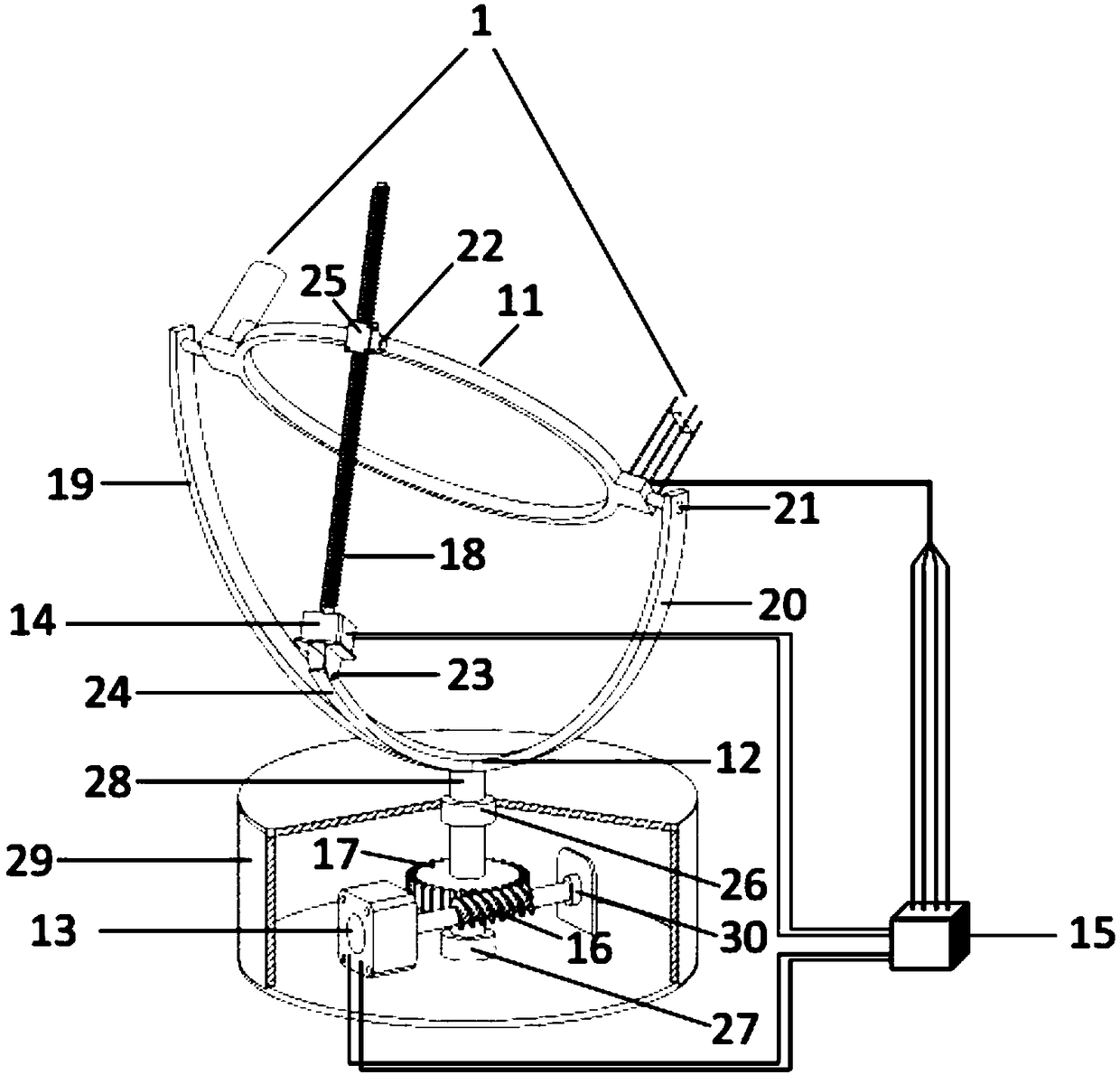
[0033] Such as figure 1 Shown: the structural representation of the sun tracking system of the present invention, 1 is a sensor unit, 11 is a two-degree-of-freedom light-receiving plate, 15 is a controller unit, and 13 is in the horizontal plane of the driving double-degree-of-freedom light-receiving plate of the driver unit (the first degree of freedom, 14 is the stepper motor that drives the two-degree-of-freedom light-receiving plate of the driver unit to rotate in pitch (the second degree of freedom, the same below), and 12 is the...


PUM


Abstract

The invention discloses a solar tracking system and method. The solar tracking system comprise a sensor unit, a controller unit, a driver unit and a mechanical unit, wherein the sensor unit is fixed on a two-degree-of-freedom light receiving plate, and the two-degree-of-freedom light receiving plate is an assembly of the mechanical unit. According to the solar tracking system, a sunshine incidencedeflection angle is sensed by virtue of the sensor unit, a light intensity signal is converted into a voltage signal to be input into the controller unit, the controller unit controls the driver unit, and the driver units drives the mechanical unit to adjust the two-degree-of-freedom light receiving plate and the sensor unit to directly face towards the sun. The solar tracking method comprises the steps of carrying out rough adjustment tracking on large-angle deviation of a sunshine incidence angle, and carrying out fine adjustment tracking on a small-angle deviation of the sunshine incidenceangle. According to the fine adjustment tracking, high light-density beams are converged by virtue of a lens system, and an optical lever is formed by virtue of the reflection of a plane mirror, so that the large-displacement deviation of the high light-density beams received in the sensor unit during the small-angle deviation of the sunshine incidence angle, the sensitivity of the sensor is improved, and the fine adjustment tracking is realized.

Description

technical field [0001] The invention belongs to the field of sun tracking technology and solar energy application, and in particular relates to an application system for real-time tracking of sun azimuth and a method for real-time tracking of sun azimuth. Background technique [0002] Solar energy is a kind of green energy. In order to efficiently apply and convert solar energy, most solar energy application devices (including but not limited to solar collectors, solar power generation devices, the same below) need to receive the maximum incident light intensity of sunlight in real time, so as to This ensures that the maximum light energy is received in real time, which requires the implementation of sun tracking and control for solar energy applications. [0003] The methods for implementing solar tracking and controlling the solar application device mainly include the sun trajectory calculation method, the GPS positioning method and the photoelectric induction method at pr...

Claims


Application Information

Patent Timeline
Patent Type & Authority Applications(China)
IPC IPC(8): G05D3/12
CPCG05D3/12
Inventor 刘丁玮熊晗杨春庄杨辉宇廖进倪强陶立新
Owner 上海极矩教育科技有限公司
Why Eureka
Try Eureka