A Design Method of Bidirectional Conjugate Tooth Profile for Harmonic Gear Transmission

A technology of conjugate tooth shape and design method, applied in the direction of components with teeth, belt/chain/gear, mechanical equipment, etc., can solve the problem of large conjugate contact area, long time consumption, double arc tooth shape design The process is cumbersome and other problems, to achieve the effect of increasing the conjugate contact area, increasing the number of tooth pairs, and increasing the range of the meshing area

CN108533715BActive Publication Date: 2020-01-21XI AN JIAOTONG UNIV
8 Cites 0 Cited by

Patent Information

Authority / Receiving Office
CN · China
Patent Type
Patents(China)
Current Assignee / Owner
Publication Date
2020-01-21

Smart Images

  • Figure 1
    Figure 1
  • Figure 2
    Figure 2
  • Figure 3
    Figure 3
Patent Text Reader

Abstract

The invention relates to a bidirectional conjugate tooth profile design method for harmonic gear drive. The bidirectional conjugate tooth profile design method for harmonic gear drive comprises the steps of firstly, expressing a flexible wheel top-section convex tooth profile coordinate through a parameter equation, converting to a rigid wheel coordinate system, solving to obtain discrete point coordinates of a theorical conjugate concave tooth profile and a concave tooth profile of a flexible wheel top-section convex tooth profile, determining the working tooth depth of a rigid wheel tooth profile through least square fit, determining a fitted curve section to be a rigid wheel bottom-section concave tooth profile and a rigid wheel top-section concave tooth profile, and calculating to accomplish a tooth profile design of a rigid wheel; and then expressing a rigid wheel top-section convex tooth profile coordinate through a parameter equation, converting to a flexible wheel coordinate system, solving to obtain discrete point coordinates of a theorical concave conjugate tooth profile in a flexible wheel bottom-section range, determining the tooth depth of a flexible wheel through least square fit, determining a fitted curve to be a flexible wheel bottom-section concave tooth profile, and calculating to obtain a flexible wheel working tooth profile. According to the bidirectional conjugate tooth profile design method for harmonic gear drive provided by the invention, the flexible wheel tooth profile and the rigid wheel tooth profile with bi-conjugate and secondary-conjugate phenomena are directly obtained, so that a conjugate contact area and a meshing zone are increased, the tooth surface contact stress is reduced, and the drive accuracy of a harmonic reducer is improved.
Need to check novelty before this filing date? Find Prior Art

Description

technical field

[0001] The invention relates to the technical field of harmonic reducers, in particular to a bidirectional conjugate tooth shape design method for harmonic gear transmission. Background technique

[0002] Harmonic transmission technology mainly uses the elastic deformation wave of the flexible working member to realize motion or power transmission. Due to the difference in the number of teeth between the flex spline and the rigid spline, during the rotation of the wave generator, the flex spline and the rigid spline move with staggered teeth. Thereby realizing power transmission. The tooth shape of the flexible spline and rigid spline in the harmonic reducer has a great influence on the performance. The involute tooth profile is widely used in harmonic gear transmission due to its good manufacturability, but the involute tooth profile is not a conjugate tooth profile, and the contact surface between the flexible spline profile and the rigid spline profile is...

Examples

Embodiment Construction

[0022] The present invention will be described in detail below in conjunction with the accompanying drawings and embodiments.

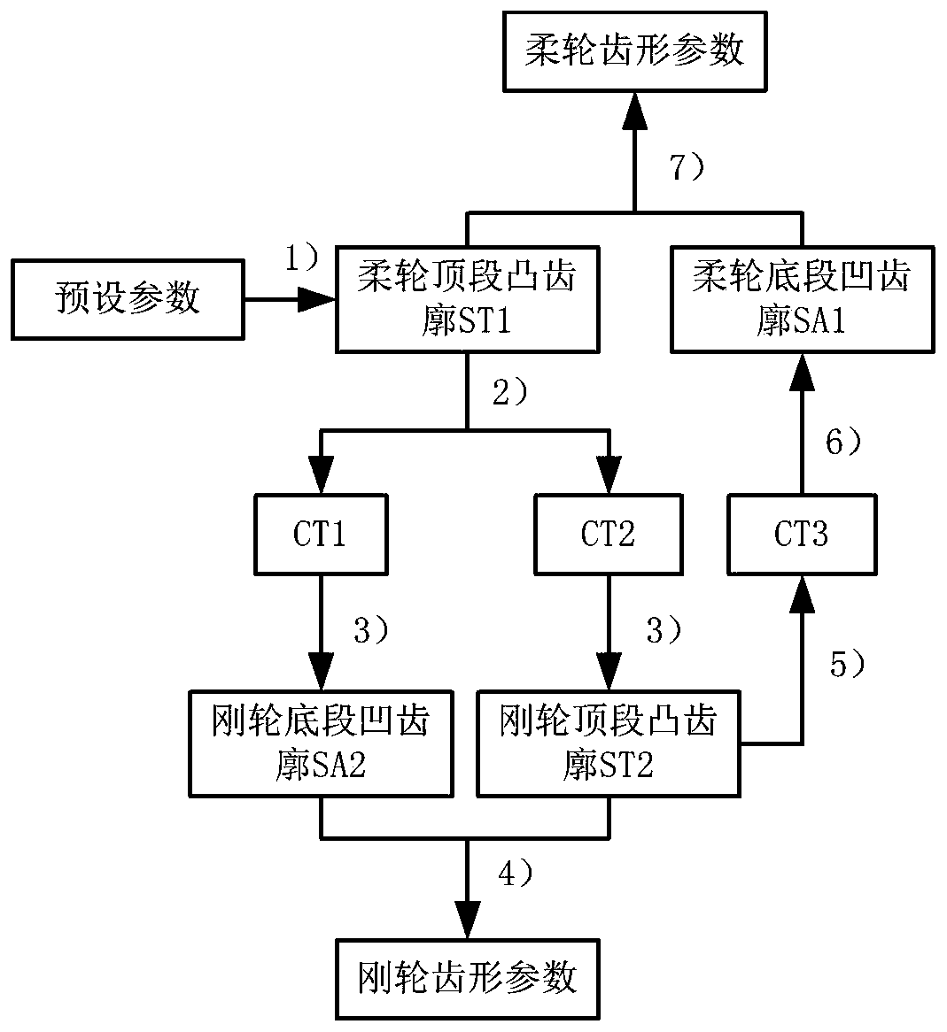
[0023] Taking the double-arc tooth shape design of harmonic gear transmission as an example, refer to figure 1 , a bidirectional conjugate tooth profile design method for harmonic gear transmission, comprising the following steps:

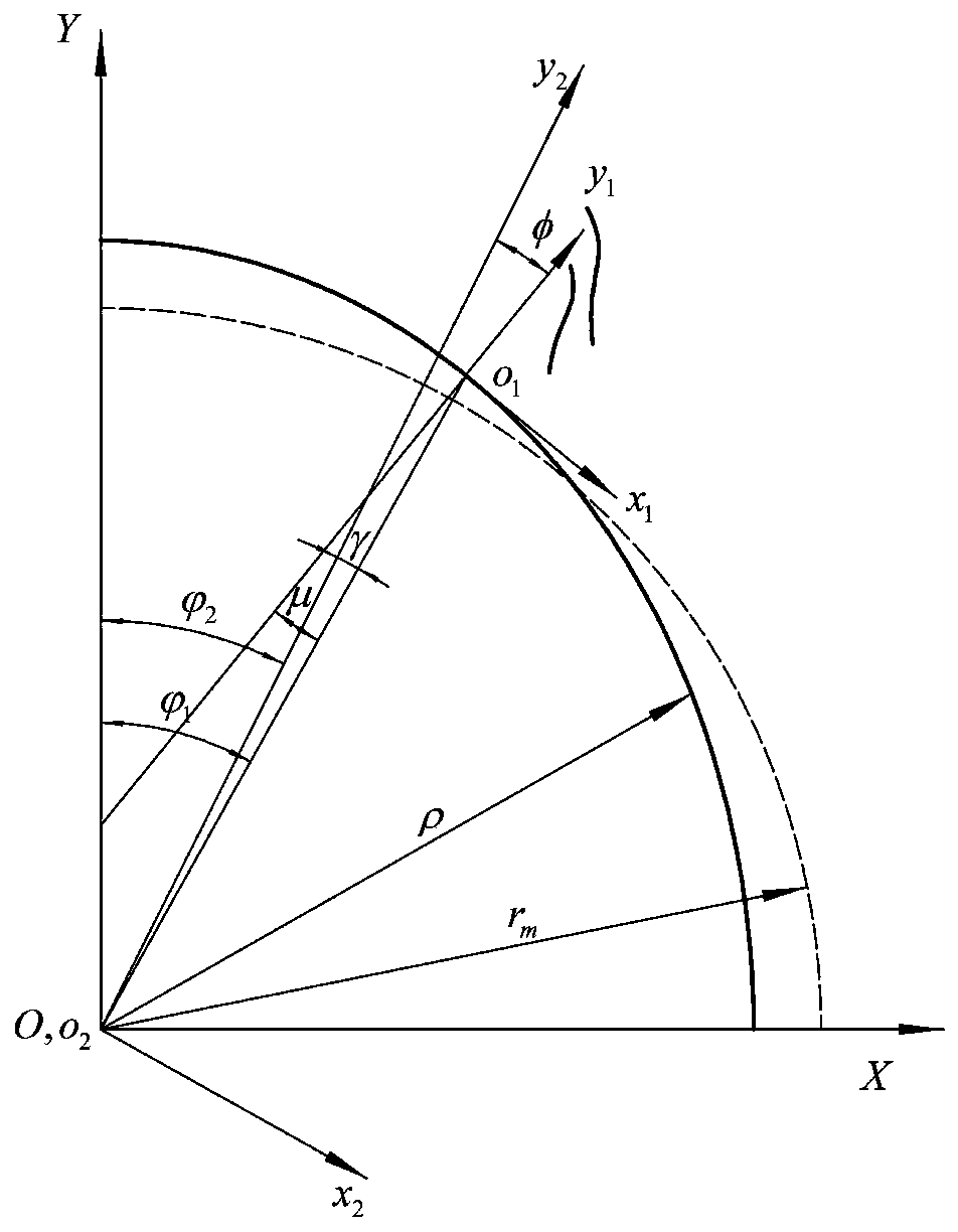
[0024] 1) First complete the design of the structural parameters according to the load and other requirements, and then determine the meshing parameters of the tooth shape to be designed; figure 2 As shown, first establish each coordinate system, establish the coordinate system {OXY} of the wave generator, the origin is located at the rotation center of the wave generator, the Y axis coincides with the long axis of the wave generator, and the X axis coincides with the short axis of the wave generator; establish the flexspline Gear tooth coordinate system {o 1 x 1 the y 1}, its y 1 The axis coincides with the center l...