Porous distributing valve for continuous adsorption exchange equipment

A technology for adsorption exchange and distribution valves, applied in the direction of improving process efficiency, etc., can solve the problems of easy wear of PTFE gaskets, difficulty in ensuring sealing, sealing leakage, etc., achieve simple transmission and control, avoid work stagnation, maintenance Easy care effect

Inactive Publication Date: 2012-09-12
工信华鑫科技有限公司
View PDF9 Cites 0 Cited by
  • Summary
  • Abstract
  • Description
  • Claims
  • Application Information

AI Technical Summary

Problems solved by technology

[0006] c) The plane seal is easy to wear, and there will be a phenomenon of cross-flow between the flow channels of each column;
[0007] d) The transmission and control are complex and energy-consuming;
[0008] e) High maintenance cost
[0009] We dissect, research and analyze foreign continuous ion exchange equipment, and think that the main reasons are: first, it is a flat seal, and the gasket is polytetrafluoroethylene. The flat seal of this material requires a lot of pressure to make the tetrafluoro gasket deform to a certain extent. The second is that the general processing accuracy is difficult to guarantee its tightness. Under pressure, the two-way steel lower valve plate of the porous distribution valve presses the PTFE gasket on the upper valve plate tightly, so that the PTFE gasket produces Micro-deformation, jamming into the valve hole, during the relative rotation process, the PTFE gasket is easy to wear, so that the material and liquid in each hole will leak to each other. This leakage is not easy to detect, so it is more harmful and easy to cause product damage Quality decline, eluent, regenerating fluid consumption increases, etc.; third, the imported flat seal continuous separation device is generally a problem of seal leakage, which is quite troublesome to replace or repair, and can only be repaired by disassembling the valve body completely.

Method used


Image

  • Porous distributing valve for continuous adsorption exchange equipment
  • Porous distributing valve for continuous adsorption exchange equipment
  • Porous distributing valve for continuous adsorption exchange equipment

Examples


Embodiment Construction

[0052] In order to make the technical problems, technical solutions and beneficial effects solved by the present invention clearer, the present invention will be further described in detail below in conjunction with the accompanying drawings and embodiments. It should be understood that the specific embodiments described here are only used to explain the present invention, not to limit the present invention.

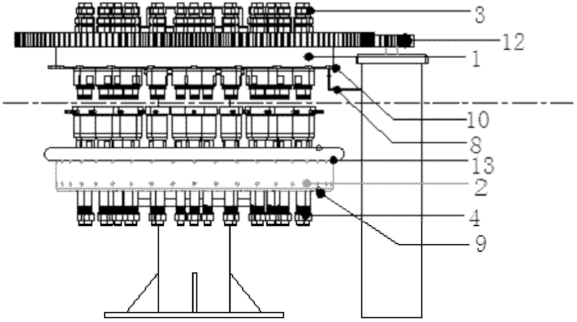
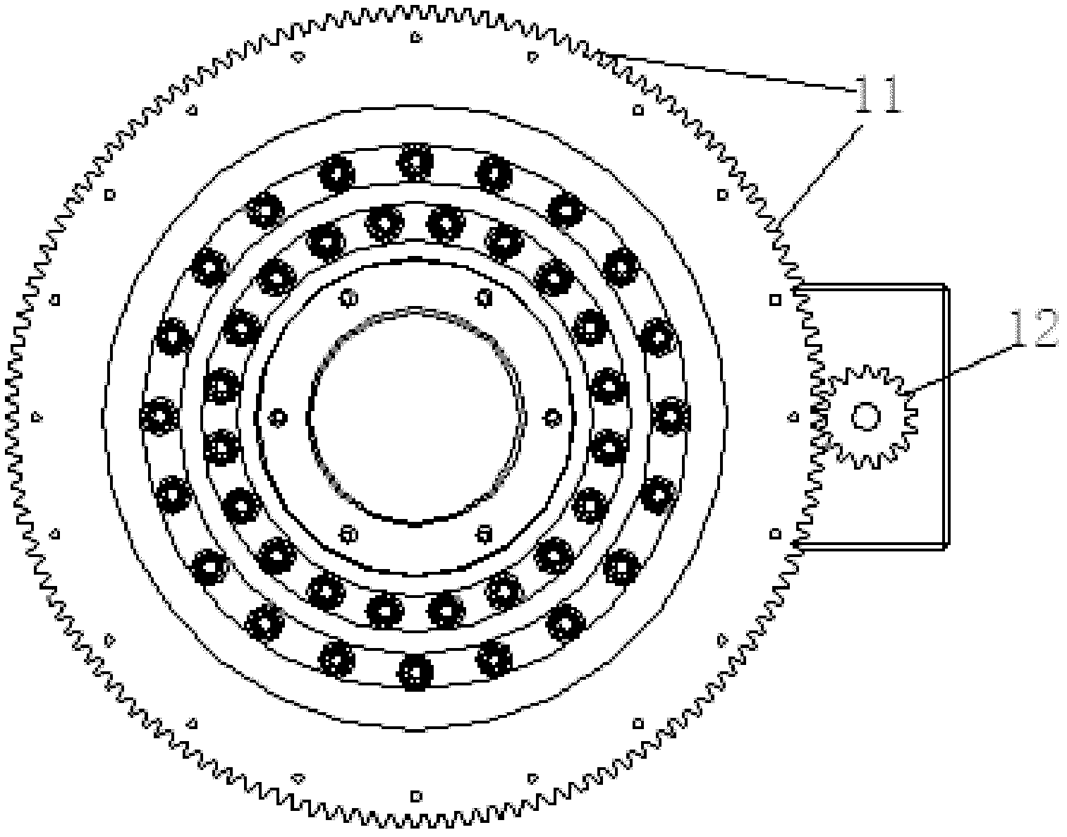
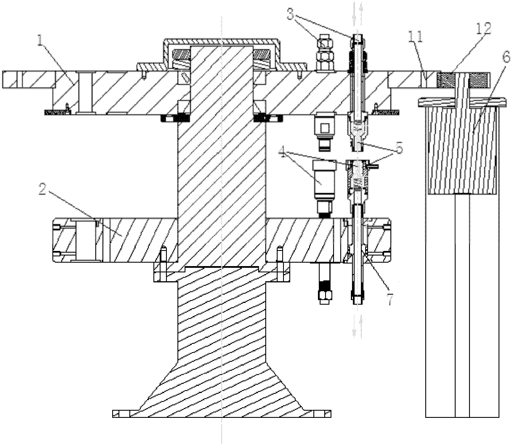
[0053] Such as Figure 1 to Figure 3 A porous distributing valve for continuous adsorption exchange equipment is shown, including a rotating disk 1, a fixed disk 2, a fixed valve 3 and a movable valve 4, and the rotating disk 1 is rotatable with respect to the coaxial center of the fixed disk 2 Set, the fixed valve 3 is fixed on the rotating disk 1, and the movable valve 4 is slidably arranged on the fixed disk 2; the fixed valve 3 and the movable valve 4 are equal in number and paired, each The arrangement and installation angle of each of the fixed valves 3 and the mo...


PUM


Abstract

A porous distributing valve for continuous adsorption exchange equipment comprises a turning disc, a fixed disc, fixed valves and movable valves, wherein the turning disc is coaxially and rotationally arranged relative to the fixed disc; the fixed valves are fixed on the turning disc; the movable valves are arranged on the fixed discs in a sliding manner; the number of the fixed valves and the number of the movable valves are the same, and the fixed valves and the movable valves are arranged in pairs; the fixed valves are matched with the movable valves paired with the fixed valves in arrayment and mounting angle; and movable water passing plugs, which are matched with one another and used for self-sealing, are arranged at one ends, which are in abutting joint with the movable valves, of the fixed valves. The porous distributing valve has a simple structure and low cost, and the cost is only one third of that of equipment from abroad; since runners on columns are independently sealed,the defect that a large-diameter planar sealing pad is easy to wear is overcome; columns have more combination forms, and can be used for treating several different leaching liquors simultaneously; the transmission and the control are simple, and the energy consumption is low; and the maintenance and the repair are simple, and the operation cost is low.

Description

technical field [0001] The invention relates to the technical field of hydrometallurgical heavy metal highly refined electrowinning, in particular to a porous distribution valve used in continuous adsorption exchange equipment. Background technique [0002] Continuous ion exchange is a world-recognized advanced separation technology. my country's continuous ion exchange equipment was introduced from Finland by a company in Xiamen around 2002. It is first applied in the purification of antibiotics and Vc in the pharmaceutical industry, and then gradually applied in biological extraction, food and beverage, chemical industry and environmental protection. However, the cost of the equipment is expensive, and it is difficult to popularize and apply it in hydrometallurgy. [0003] Disadvantages of foreign continuous ion exchange equipment: [0004] a) The structure is complex and the cost is high. The price of a continuous ion exchange equipment that can process 5,000 cubic met...

Claims


Application Information

Patent Timeline
Patent Type & Authority Applications(China)
IPC IPC(8): C22B3/42C22B3/02
CPCY02P10/20
Inventor 邱建宁徐纯理赵路李新华杨斗
Owner 工信华鑫科技有限公司
Why Eureka
Try Eureka