Low voltage ride through control method and device of photovoltaic grid-connected inverter

A low-voltage ride-through and control method technology, which is applied in the direction of output power conversion devices, photovoltaic power generation, circuit devices, etc., can solve problems such as current fluctuation distortion, neglect control, and influence on output power quality, so as to improve reliability and prevent voltage transients. The effect of small drop and current fluctuation

Active Publication Date: 2013-08-14
BOE TECH GRP CO LTD +1
View PDF3 Cites 27 Cited by
  • Summary
  • Abstract
  • Description
  • Claims
  • Application Information

AI Technical Summary

Problems solved by technology

[0007] At present, in the low-voltage ride-through control method and device of photovoltaic grid-connected inverters, the control of the output current of the inverter is ignored, resulting in serious current fluctuations and distortions when the voltage drops sharply, and the output power quality is seriously affected. , so the low-voltage ride-through control method and control device of the photovoltaic grid-connected inverter need to be further optimized and improved

Method used


Image

  • Low voltage ride through control method and device of photovoltaic grid-connected inverter
  • Low voltage ride through control method and device of photovoltaic grid-connected inverter
  • Low voltage ride through control method and device of photovoltaic grid-connected inverter

Examples


Embodiment 1

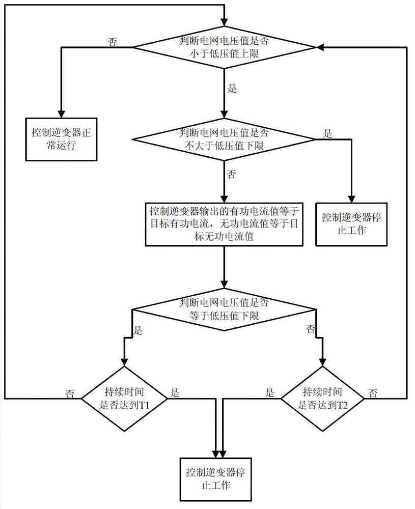
[0061] The low-voltage ride-through control method of the photovoltaic grid-connected inverter in this embodiment includes the following steps:

[0062] Step S1: Determine whether the grid voltage value is less than the upper limit of the low voltage value, usually the upper limit of the low voltage value is 0.9 times the rated voltage,

[0063] If not, control the normal operation of the inverter. If the effective voltage value of the grid is greater than or equal to the upper limit of the low voltage value, it means that there is no voltage sag in the photovoltaic grid-connected at this time, and it is in a normal working state, so the inverter normal operation of the device;

[0064] If yes, go to step S2;

[0065] Step S2: Determine whether the grid voltage value is not greater than the lower limit of the low voltage value; usually the lower limit of the low voltage value is 0.2 times the rated voltage

[0066] Yes, control the inverter to stop working; if the voltage va...

Embodiment 2

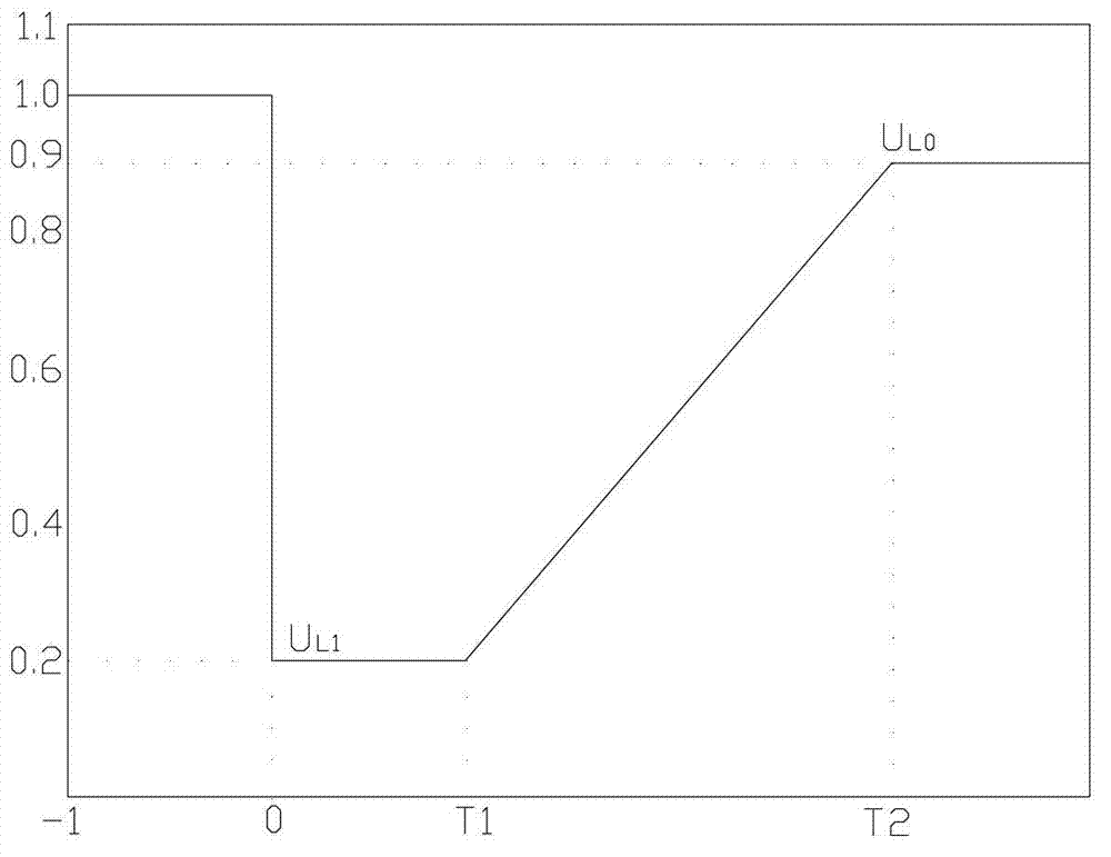
[0070] Such as figure 1 As shown, the photovoltaic grid-connected inverter certification testing standard "Technical requirements and test methods for grid-connected photovoltaic power generation inverters" CGC:2010 stipulates that medium and high voltage inverters specially suitable for large-scale photovoltaic power plants should have certain The ability to withstand abnormal voltage, to avoid disconnection when the grid voltage is abnormal, causing instability of the grid power supply, the following requirements are made;

[0071] Among them, U L0 is the low voltage upper limit for normal operation;

[0072] u L1 is the lower limit of low pressure that needs to be tolerated;

[0073] T1 is the voltage drop to U L1 The time required to maintain grid connection;

[0074] T2 is the voltage drop to U L0 The time required to maintain grid connection.

[0075] u L1 , T1, T2 values ​​need to consider the protection and reclosing action time and other actual conditions, usu...

Embodiment 3

[0092] In this embodiment, on the basis of one of the above two embodiments, the low-voltage ride-through control method of the photovoltaic grid-connected inverter further includes the steps of collecting voltage and current signals on the DC side and collecting voltage and current signals on the AC side power grid S0;

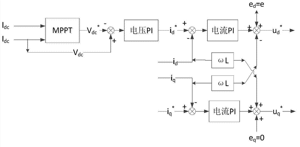
[0093] In the step S1, when the grid voltage is not less than the upper limit of the low-voltage value, the active current value normally output by the control inverter is equal to the normal target current obtained through the MPPT algorithm and voltage PI control based on the signal collected in step S0, and the reactive current value is zero. .

[0094] Step S1 can be before step S1 or after step S1, as long as it is guaranteed to be before step S2.

[0095] The control program or controller calculates the normal target voltage value of the inverter in normal operation through the MPPT: Maximum Power Point Tracking algorithm based on the DC voltage and DC...


PUM


Abstract

The invention discloses a low voltage ride through control method and device of a photovoltaic grid-connected inverter, and is designed to solve the problem of poor ride through stability caused by neglecting control of a current waveform and an amplitude when the low voltage ride through control is performed on the inverter in the prior art. The method includes the steps as follows: step S1, whether a voltage value of a power grid is smaller than the upper limit of a low voltage value is judged, if the voltage value of the power grid is smaller than the upper limit of the low voltage value, the step S2 is executed, and otherwise, the inverter is controlled to work normally; step S2, whether the voltage value of the power grid is not more than the lower limit of the lower value is judged, if the voltage value of the power grid is not more than the lower limit of the lower value, the inverter is controlled to stop working, and otherwise, an active power current value output by the inverter is controlled to be equal to a target active power current value and the output reactive power current value is equal to a reactive power current value; and a comparison difference value of a total current output by the inverter and a current output by a photovoltaic grid in a normal state is smaller than a preset value. The change of total currents before and after voltage sag is small by controlling an active power current and a reactive power current of the inverter, so that the functions of supporting and stabilizing the power grid are realized.

Description

technical field [0001] The field of power control of the present invention, in particular, relates to a control method and device for photovoltaic grid-connected inverters Background technique [0002] Photovoltaic grid connection refers to the power network in which solar cell arrays or photovoltaic power plants are integrated into the grid to achieve power supply. [0003] An inverter is a device used to convert direct current into alternating current. [0004] Low Voltage Ride Through (LVRT: Low Voltage Ride Through) means that when a voltage sag occurs in the photovoltaic grid-connected power network, the DC side, such as a photovoltaic power station, can maintain the connection with the AC side grid, supporting the recovery of the grid fault, so as to ride through the voltage drop time, In order to avoid the expansion of power grid faults and improve the reliability of power supply. [0005] Voltage sag refers to an unexpected event in which the effective value of the...

Claims


Application Information

Patent Timeline
Patent Type & Authority Applications(China)
IPC IPC(8): H02J3/38H02M1/00
CPCY02E10/563H02J3/1814H02J2300/26H02J3/381Y02E10/56Y02E40/10H02M1/0003H02M1/36H02M7/44
Inventor 郑平宋行宾韩晓艳
Owner BOE TECH GRP CO LTD
Why Eureka
Try Eureka