
A device for recovering and discharging anesthesia ether waste gas
A waste gas recovery and discharge device technology, which is applied in the field of medical equipment, can solve problems such as pollution and harmful anesthesia waste gas, and achieve the effects of low cost, convenient operation and simple structure
- Summary
- Abstract
- Description
- Claims
- Application Information
AI Technical Summary
Problems solved by technology
Method used
Image

Examples
Embodiment 1
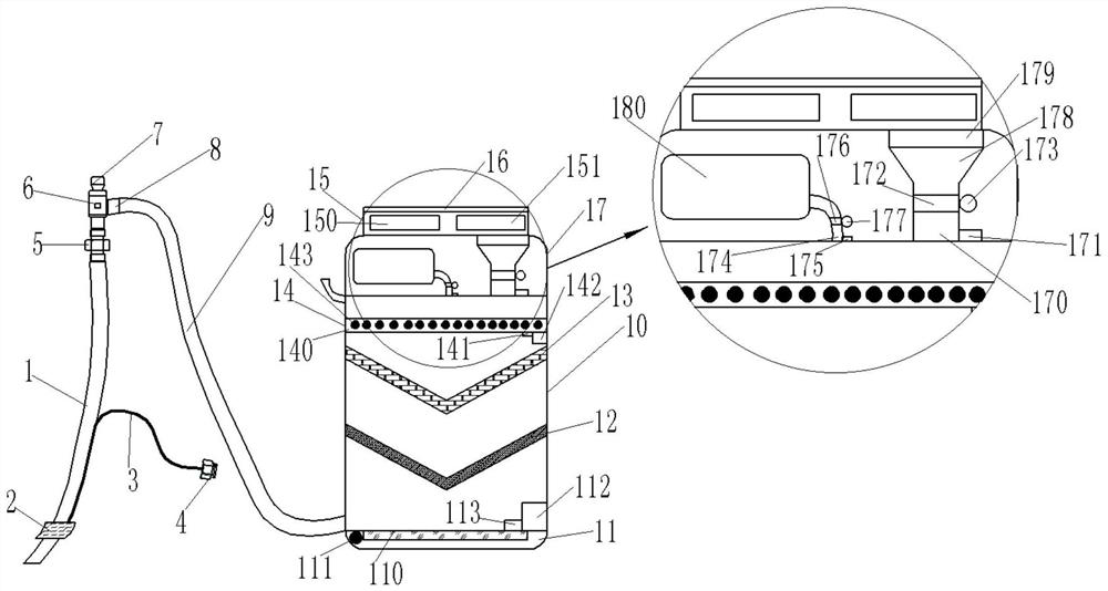
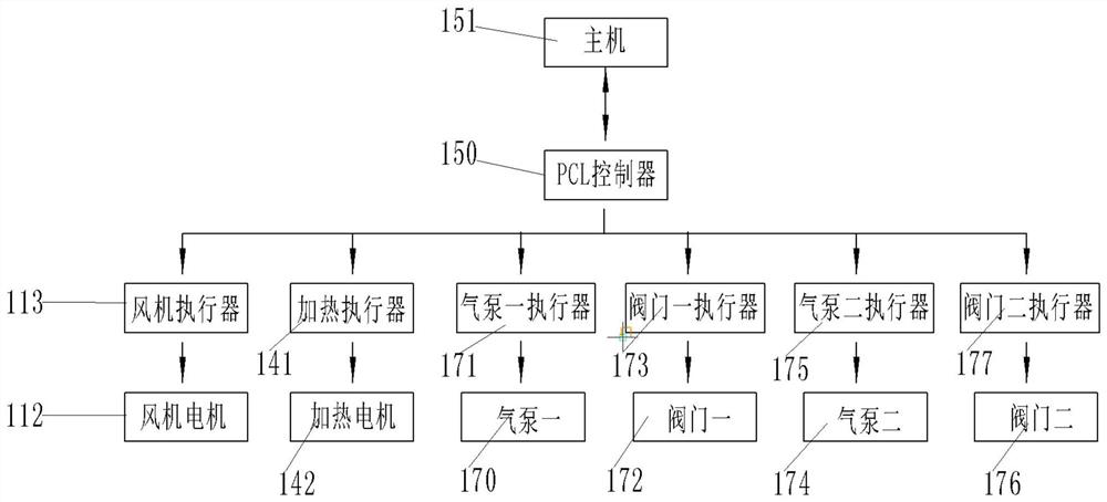
[0022] Such as figure 1As shown, a device for recovery and discharge of anesthesia ether waste gas mainly includes: trachea 1, cuff 2, injection connection pipe 3, injection port 4, joint 5, negative pressure pump 6, connection pipe 9, collector 10, The main engine 15, the digital display panel 16, the cuff 2 is installed at the bottom of the trachea 1, the cuff 2 is connected to the injection port 4 through the injection connection tube 3, the top of the trachea 1 is connected to the negative pressure pump 6 through the joint 5, and the negative pressure The pump 6 is provided with an air inlet 7 and an exhaust port 8, and the exhaust port 8 is connected to the collector 10 through a connecting pipe 9. The digital display panel 16 is installed on the top surface of the collector 10. The collector 10 includes: a fan 11, The first filter layer 12, the second filter layer 13, the decomposition chamber 14, the collection chamber 17, the fan 11 is installed on the inner bottom sur...
PUM
| Property | Measurement | Unit |
|---|---|---|
| boiling point | aaaaa | aaaaa |
Abstract
Description
Claims
Application Information