A device and method for hydraulically measuring the demoulding performance of concrete

A technology of demoulding performance and concrete is applied in the field of hydraulic devices for measuring the demoulding performance of concrete, which can solve the problems of inability to realize precise control and monitoring of air pressure changes, time-consuming and laborious operation, complicated equipment cost, etc., saving time and energy, Overcome expensive equipment and improve accuracy and reliability

Active Publication Date: 2021-02-19
HARBIN INST OF TECH
View PDF7 Cites 0 Cited by
  • Summary
  • Abstract
  • Description
  • Claims
  • Application Information

AI Technical Summary

Problems solved by technology

[0006] The purpose of the present invention is to provide a device and method for hydraulically measuring the demoulding performance of concrete to solve the problem that the existing method for evaluating the demoulding performance of concrete is not accurate enough, and the operation is time-consuming and laborious. Effectively and completely separated from the concrete mold, the precise control and monitoring of air pressure changes cannot be realized. In addition, the equipment used is complicated and expensive.

Method used


Image

  • A device and method for hydraulically measuring the demoulding performance of concrete
  • A device and method for hydraulically measuring the demoulding performance of concrete
  • A device and method for hydraulically measuring the demoulding performance of concrete

Examples


specific Embodiment approach 1

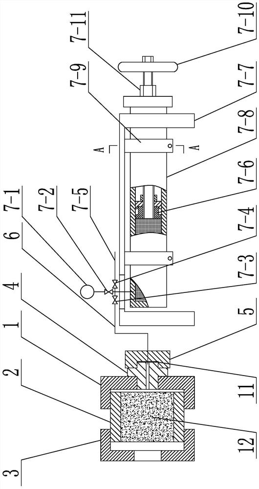
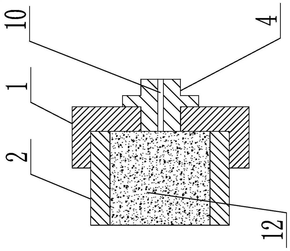
[0028] Specific implementation mode one: combine figure 1 , figure 2 , image 3 , Figure 4 and Figure 5Describe this embodiment, this embodiment includes first installation cover 1, concrete mold 2, second installation cover 3, middle piece 4, connecting pipe 6 and hydraulic pump, described first installation cover 1 and second installation cover 3 vertical Arranged side by side, the concrete mold 2 is arranged between the first installation cover 1 and the second installation cover 3, the two ends of the concrete mold 2 are detachably connected with the first installation cover 1 and the second installation cover 3 respectively, the concrete mold 2 is provided with concrete 12, one end of the middle piece 4 passes through the first installation cover 1 and communicates with the concrete 12 in the concrete mold 2, and the other end of the middle piece 4 communicates with the oil outlet of the hydraulic pump through the connecting pipe 6.

[0029] Adding the second insta...

specific Embodiment approach 2

[0035] Specific implementation mode two: combination figure 1 , figure 2 and image 3 To illustrate this embodiment, first place the concrete mold 2 vertically, screw its lower end with the first installation cover 1, and connect the internal thread of the first through hole 8 with the external thread of the middle piece 4, and assemble the concrete mold 2 Add a layer of plastic film to the bottom of the concrete mold 2, apply a release agent on the inner wall of the concrete mold 2, then fill the concrete mold 2 with concrete 12 that meets the standard requirements, and place it under standard curing conditions for at least 24 hours; after curing After the upper end of the concrete mold 2 is screwed to the second installation cover 3, the concrete mold 2 is placed horizontally, and the first installation cover 1 is unscrewed, so that the distance between the first installation cover 1 and the lower end of the concrete mold 2 is 5~ 10mm, so that the test gap is formed betwe...

Embodiment 1

[0038] Embodiment one: the concrete mold 2 is a steel pipe, its inner diameter is 200mm, the radius R=100mm, the height H is 200mm, and the diameter of the first through hole 8 is 50mm. First, the concrete mold 2 is vertically placed, and its lower end is connected with the first installation The cover 1 is threaded, the internal thread of the first through hole 8 is connected with the external thread of the middle piece 4, and a layer of plastic film is added to the bottom of the assembled concrete mold 2 to ensure that the concrete 12 does not enter the first hole in the middle piece 4. A through hole 10 and isolation concrete 12 are in contact with the first installation cover on the end surface, and then apply a release agent on the inner wall of the concrete mold 2, and then fill the concrete mold 2 with concrete 12 that meets the standard requirements, and place it in standard curing Under the condition of curing for at least 24 hours; after the curing is completed, after...


PUM


Abstract

A device and method for hydraulically measuring the release performance of concrete. Currently, the test block is effectively and completely separated from the concrete test mold by using an air pump manually, which cannot realize precise control and monitoring of air pressure changes. In addition, the equipment used in conjunction with the method is complicated and expensive. In the present invention, the first installation cover and the second installation cover are arranged vertically side by side, the concrete mold is arranged between the first installation cover and the second installation cover, and the two ends of the concrete mold are respectively connected to the first installation cover and the second installation cover. The cover is detachably connected, concrete is set in the concrete mold, one end of the middle piece is connected with the concrete in the concrete mold through the first installation cover, and the other end of the middle piece is connected with the oil outlet of the hydraulic pump through the connecting pipe. The invention has reasonable structural design, timely, accurate and effective measurement effect and convenient operation. The method in the present invention is convenient to operate and easy to control. The invention is used for measuring the release performance of concrete.

Description

technical field [0001] The invention specifically relates to a device and method for hydraulically measuring the release performance of concrete. Background technique [0002] At present, my country has formulated the release agent standard JC / T949-2005 for concrete products. The quality evaluation index of the release agent mainly considers homogeneity and construction performance. Homogeneity refers to density, viscosity, PH value, solid content or Stability and construction performance refer to drying film forming time, mold release performance, water resistance, corrosion effect on steel molds, limit service temperature or other indicators. Concrete release agent refers to a substance applied on the construction formwork before concrete pouring, so that the formwork will not stick to the concrete surface after pouring, easy to remove the formwork, and will not affect the smoothness of the concrete surface. Its main function is to form a film on the surface of formwork an...

Claims


Application Information

Patent Timeline
Patent Type & Authority Patents(China)
IPC IPC(8): G01N3/08G01N3/24G01N19/04
CPCG01N3/08G01N3/24G01N19/04G01N2203/0017G01N2203/0025
Inventor 杨英姿刘雨时张歌
Owner HARBIN INST OF TECH
Why Eureka
Try Eureka