Eureka AIR delivers breakthrough ideas for toughest innovation challenges, trusted by R&D personnel around the world.

A sensor capable of reducing errors and its measuring method

A sensor and error technology, applied in the field of sensors, can solve the problems of difficulty in determining whether the voltage signal corresponds to the real pressure value, the incomplete coincidence of the loading line and the unloading line, and the low accuracy of the pressure signal, so as to avoid uncertain problems and have a simple structure. , the effect of a large measurement range

Active Publication Date: 2016-10-05
NANJING GAOHUA TECH
View PDF4 Cites 0 Cited by
  • Summary
  • Abstract
  • Description
  • Claims
  • Application Information

AI Technical Summary

Problems solved by technology

However, when measuring high-precision air pressure, the mechanical hysteresis error of the pressure sensor itself cannot be ignored.
When the pressure applied to the diaphragm transmitting pressure drops from high to low to the pressure value F, and when the pressure rises from low to high to the pressure value F, although the final pressure value is the same, due to mechanical hysteresis, the diaphragm The bending deflection under the same stress is different, that is, the loading line and unloading line of the diaphragm load of the sensor do not completely coincide
For the pressure sensor, since the small change trend of the pressure to be measured is random, it is difficult to determine whether the measured voltage signal corresponds to the real pressure value, which causes the pressure corresponding to the measured diaphragm deformation to deviate from the actual pressure. The accuracy of the pressure signal received is not high

Method used


Image

  • A sensor capable of reducing errors and its measuring method
  • A sensor capable of reducing errors and its measuring method

Examples


Embodiment Construction

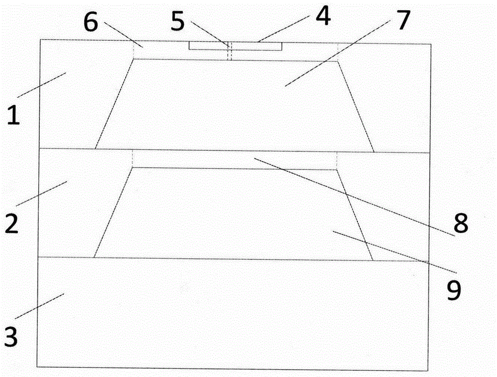
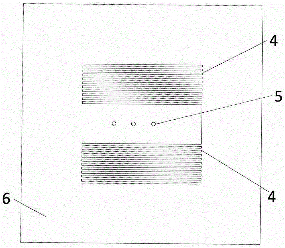
[0009] Control attached figure 1 , the sensor consists of a first substrate 1, a second substrate 2, a third substrate 3, a heating resistor 4, a through hole 5, a diaphragm 6 of the first substrate, a cavity 7 of the first substrate, a diaphragm 8 of the second substrate, The cavity 9 of the second substrate is formed. Wherein the first substrate 1 is connected with the second substrate 2, the second substrate 2 is connected with the third substrate 3, the cavity 9 of the second substrate is located at the junction of the second substrate 2 and the third substrate 3, and the cavity is a closed vacuum Cavity: The cavity 7 of the first substrate is located at the junction of the first substrate 1 and the second substrate 2, and the through hole 5 connects the gas in the cavity 7 of the first substrate with the outside air.

[0010] control figure 2 The diaphragm 6 of the first substrate has a heating resistor 4 and a through hole 5, and the heating resistor 4 is placed at bo...


PUM


Abstract

The invention discloses a sensor capable of reducing error and a measuring method thereof. The sensor comprises a first base plate, a second base plate, a third base plate, a heating resistor, a through hole, a membrane of the first base plate, a cavity of the first base plate, a membrane of the second base plate and a cavity of the second base plate. The measuring method comprises the following steps: heating the cavity of the first base plate by electrifying the heating resistor, wherein the air in the cavity of the first base plate thermally expands to pressurize the membrane of the second base plate; reducing the heating power of the heating resistor; and measuring the pressure on the membrane of the second base plate. Through the above steps, the membrane on the second base plate can be maintained on an unloading line of a mechanical anhysteretic carve, so that the problem that the position of the membrane is uncertain can be avoided, the error caused by mechanical anhysteretic offset is suppressed, and the measurement precision of the pressure sensor is improved.

Description

technical field [0001] The invention relates to the technical field of sensors, in particular to a structure and a method for solving the mechanical hysteresis error of a gas pressure sensor. Background technique [0002] Gas pressure measurement is widely used in many industrial equipment such as industrial instruments, medical appliances, barometers, altimeters, pressure switches, and inflatable equipment. Traditional air pressure sensors, such as mercury barometers, aneroid barometers, etc., have the defects of large volume and low precision, which limit the scope of application. With the development of micro-electromechanical MEMS technology, the technology of MEMS pressure sensor has also been developed and significantly improved. The sensor volume is getting smaller and smaller, and the measurement accuracy has also been greatly improved. However, when measuring high-precision air pressure, the mechanical hysteresis error of the pressure sensor itself cannot be ignore...

Claims


Application Information

Patent Timeline
Patent Type & Authority Patents(China)
IPC IPC(8): G01L9/00
Inventor 李维平刘清惓黄标周晓佘德群
Owner NANJING GAOHUA TECH
Why Eureka
Eureka Blog
Learn More