
Changeover valve

A technology for switching valves and valve seats, used in multi-port valves, valve devices, engine components, etc., to solve problems such as wrong assignment of operating rods, changes in owner's plans, and wrong installation of wall connection housings

Active Publication Date: 2018-10-23
FLUHS DREHTECHN
View PDF5 Cites 0 Cited by
  • Summary
  • Abstract
  • Description
  • Claims
  • Application Information

AI Technical Summary

Problems solved by technology

Here it can happen that either due to an incorrect installation of the wall connection housing, or also due to a change in the owner's plans, after the installation of the valve upper part in the wall connection housing, the position of the spindle of the valve upper part is assigned incorrectly or is incompatible with Wrong assignment of joystick to spindle connection

Method used


Image

  • Changeover valve
  • Changeover valve
  • Changeover valve

Examples


Embodiment Construction

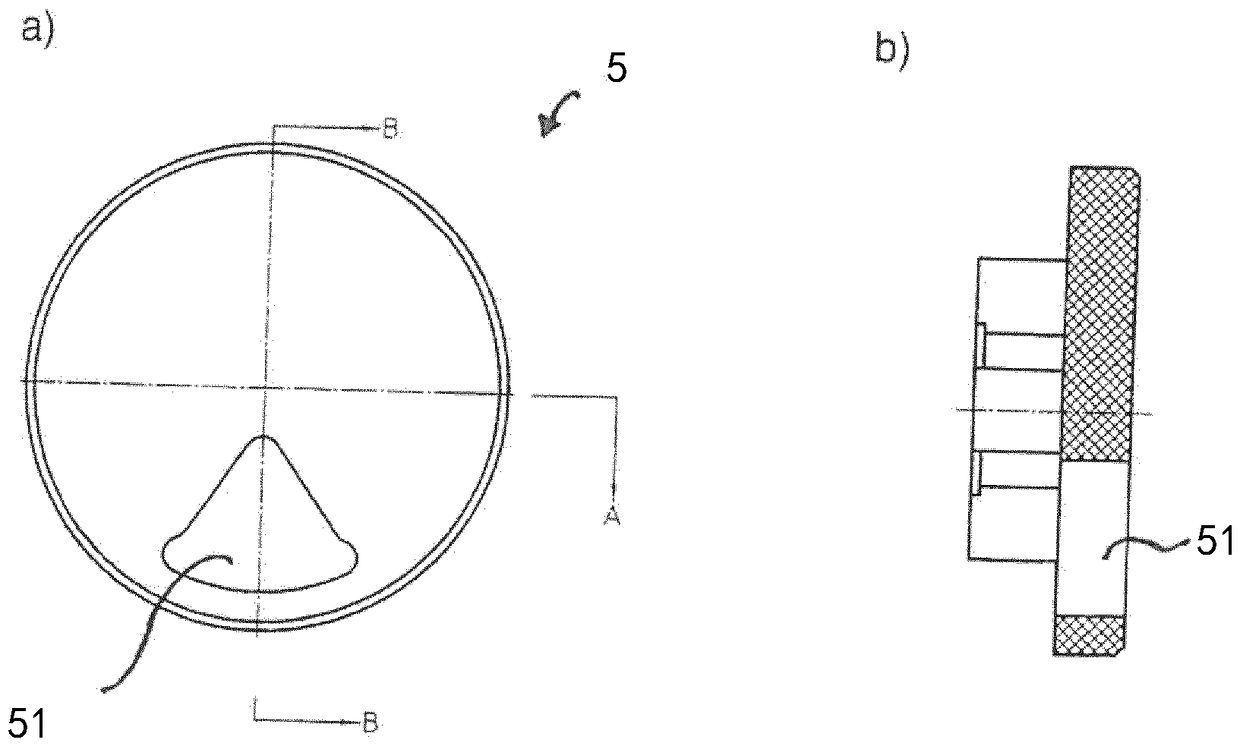
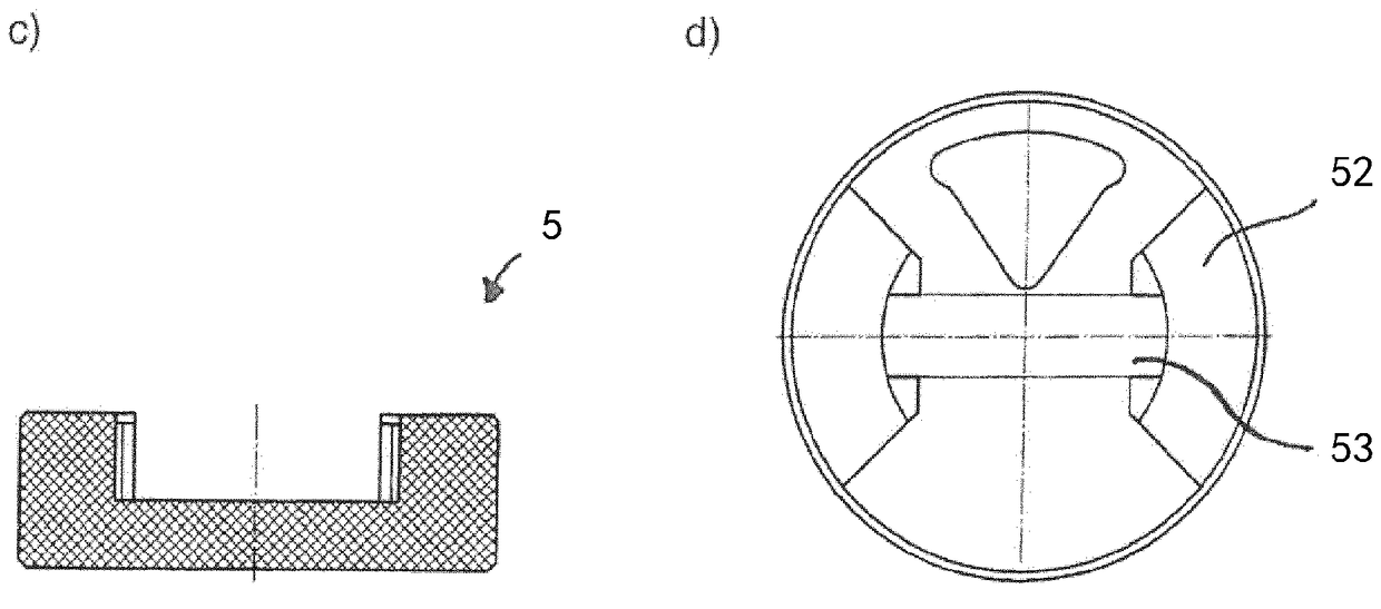
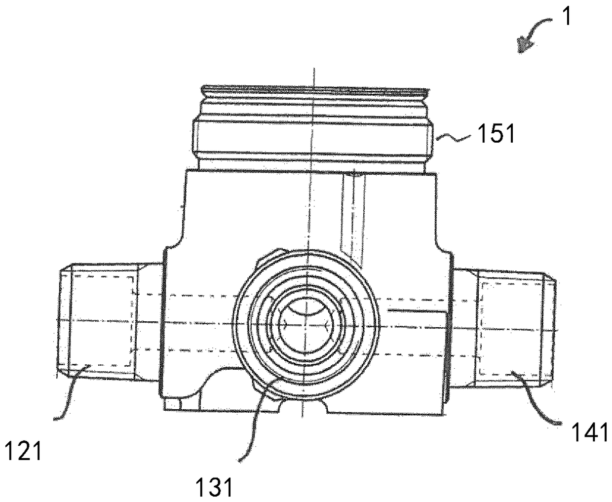
[0033] The switchover valve chosen as the embodiment essentially consists of a wall connection housing 1 which accommodates the upper part 2 of the valve.

[0034] The wall connection housing 1 is made of brass in this exemplary embodiment and comprises a cup-shaped valve chamber 15 into which a valve seat 16 is inserted on the bottom side. Three outlet channels 12 , 13 , 14 , which are each connected to outlet connections 121 , 131 , 141 formed on the outside of valve chamber 15 , open into valve seat 16 offset by 120° from one another. Furthermore, an inlet connection 111 , which is connected to an inlet channel 11 , which opens laterally into the valve chamber 15 , is integrally formed on the outside of the valve chamber 15 . The input connector 111 and the three output connectors 121 , 131 , 141 are formed at the valve chamber 15 staggered from each other by 90° and are used for connecting fluid inflow or outflow lines. Furthermore, three positioning holes 17 are provided...


PUM


Abstract

The invention relates to a changeover valve comprising a wall connection housing (1) with at least one inlet channel (11) and at least three outlet channels (12, 13, 14) which open into a valve seat (16) for receiving a valve upper part (2). The valve upper part (2) has a base piece (7) with at least three outlet openings (71) which can be connected to a respective outlet channel of the at least three outlet channels (12, 13, 14) via the valve seat (16). Furthermore, the valve upper part (2) has at least one feed (32) which is connected to the at least one inlet channel (11) and which can be connected to at least one of the at least three outlet openings (71) via a control disc (5) that can be rotated relative to a stationary inlet disc (6). The control disc (5) is in engagement with a spindle (4), by means of which the control disc can be rotated. The base piece (7) has at least one positioning pin (73) which engages into a positioning bore (17) arranged in the valve seat (16). The valve seat (16) is equipped with at least two positioning bores (17) for engaging with the at least one positioning pin (73) in different assembly positions of the valve upper part (2).

Description

technical field [0001] The invention relates to a switching valve comprising a wall connection housing with at least one input channel and at least three output channels opening into a valve for receiving the upper part of the valve In the seat, the upper part of the valve has a bottom part and also has an inflow port, the bottom part has at least three output openings, and the at least three output openings can be respectively connected with the at least three output channels through the valve seat. One output channel is connected, the inlet is connected with the at least one input channel, and can be connected with at least one output opening in the at least three output openings through a control disc, and the control disc can be fixed relative to the The input disc rotates, the control disc engages with the spindle, wherein the bottom part has at least one locating pin which is inserted into at least one locating hole arranged in the valve seat. Background technique [...

Claims


Application Information

Patent Timeline
IPC IPC(8): F16K11/074
CPCF16K11/0743F16K11/025F16K11/0787F16K11/165
Inventor L.朗格
Owner FLUHS DREHTECHN
Learn More