
Sun-shading umbrella

A technology for parasols and umbrella discs, which is applied in the direction of umbrellas, clothing, walking sticks, etc., which can solve the problems that parasols are difficult to cover a large area, easy to bend or break, and the umbrella ribs are unstable, so as to increase the effective sunshade area, The effect of convenient operation and reasonable structure

Pending Publication Date: 2018-11-06
ZHEJIANG DINGSHENG OUTDOOR LIVING PROD CO LTD
View PDF1 Cites 2 Cited by
  • Summary
  • Abstract
  • Description
  • Claims
  • Application Information

AI Technical Summary

Problems solved by technology

This kind of parasol has only one umbrella top like most of the current parasols. If you need to increase the opening area, you can only lengthen the ribs or use a folding mechanism, which will increase the pressure on the umbrella ribs and the umbrella fabric, resulting in instability , easy to bend or break. In a larger application site, it is difficult to cover a larger area with limited sunshades. If you want to increase the number of sunshades, you need to set up multiple sunshades, which will inevitably increase the cost; followed by the shape old, not new enough

Method used


Image

  • Sun-shading umbrella
  • Sun-shading umbrella
  • Sun-shading umbrella

Examples


Embodiment 1

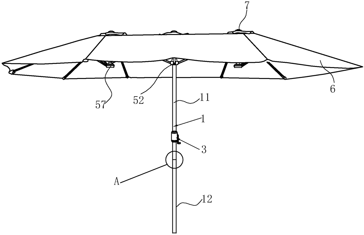
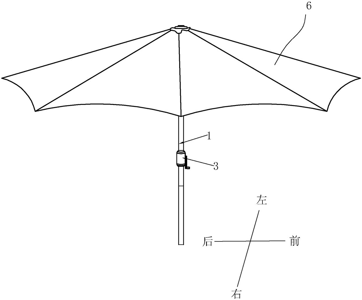
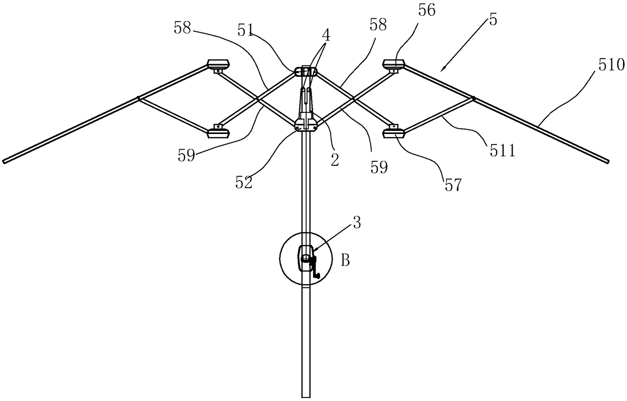
[0032] Such as Figure 1-12 Shown, a kind of parasol comprises column 1, umbrella frame 5 and umbrella cloth 6, and umbrella frame 5 comprises upper umbrella plate 51, lower umbrella plate 52, long bone umbrella plate 56 and short bone umbrella plate 57, and upper umbrella plate 51 sets On the top of the column 1, the column 1 is provided with a hand control mechanism 3 that can control the opening and closing function of the umbrella stand, and the lower umbrella plate 52 can slide up and down on the column 1 and is located between the upper umbrella plate 51 and the hand control mechanism 3;

[0033] The column 1 is formed by connecting the upper column 11 and the lower column 12, and the connection between the upper column 11 and the lower column 12 is a shrinking marble plug-in connection or a threaded socket connection, such as Figure 5.1~5.2 As shown, the upper end of the lower column 12 is narrowed, and a marble 121 is installed in the radial direction. The upper colum...

Embodiment 2

[0043] Such as figure 1 , 3 , 5 to 14, the difference from Embodiment 1 is that the length of the first long bone 53 of the umbrella stand 5 is shortened, and the length of the second long bone 54 is extended. Correspondingly, the corresponding The long bones 510 are shortened synchronously, and the corresponding long bones 510 on one side of the second long bone 54 are lengthened synchronously. In this way, with the column 1 as the center, two groups of umbrella frame structures with symmetrical front and rear eccentricity are formed, which increases the effective sunshade area of ​​the umbrella surface.


PUM


Abstract

The invention provides a sun-shading umbrella. An upper umbrella disc is hinged with two first crossed rods, a first long rib and a second long rib; a lower umbrella disc is hinged with two second crossed rods and two first short ribs; the two first crossed rods are located at left and right sides of a stand column; the first long rib and the second long rib are located at front and rear sides ofthe stand column; one first short rib is hinged to the middle part of the first long rib and the other first short rib is hinged to the middle part of the second long rib; the second crossed rods arelocated at the left and right sides of the stand column; the middle parts of the second crossed rods are hinged to the middle parts of the first crossed rods; end parts of the first crossed rods are hinged with short rib umbrella discs; end parts of the second crossed rods are hinged with long rib umbrella discs; the long rib umbrella discs are hinged with long ribs; the short rib umbrella discs are hinged with short ribs; one end of each short rib is hinged onto the corresponding short rib umbrella discs and the other end of each short rib is hinged to the middle part of the corresponding long rib; umbrella caps are arranged on the upper umbrella disc and the two long rib umbrella discs; umbrella cloth covers the long ribs to form three umbrella tops. The sun-shading umbrella is novel instructure; the area is large when the sun-shading umbrella is unfolded and the sun-shading coverage area is increased; the sun-shading umbrella has a firm and stable structure.

Description

technical field [0001] The invention relates to the technical field of outdoor sunshade umbrellas, in particular to a sunshade umbrella. Background technique [0002] Umbrellas belong to leisure household products, mainly used in leisure places such as squares, beaches, parks and courtyards, to provide people with shade, shelter from wind and rain. Parasols are generally divided into two types: central pillar parasols and side pillar parasols. Among them, central pillar parasols are deeply loved by people because of their advantages in use, storage, and transportation, and the market demand is increasing. With the improvement of living standards, sunshades with two characteristics of being easy to carry and having a large opening area are the development trend of sunshades in the future. [0003] In order to meet these two requirements, people have designed many parasols, which are suitable for various places such as beaches, courtyards, parks, families and hotel lawns, as ...

Claims


Application Information

Patent Timeline
IPC IPC(8): A45B23/00A45B25/02A45B25/14A45B25/00
CPCA45B23/00A45B25/00A45B25/02A45B25/14A45B2025/003A45B2023/0093A45B2025/146A45B2200/10
Inventor 孔成熙
Owner ZHEJIANG DINGSHENG OUTDOOR LIVING PROD CO LTD
Learn More