Special blade swinging type hydraulic cylinder for robot motion joint

A robot motion, swinging technology, applied in the directions of manipulators, mechanical equipment, engine components, etc., can solve the problems of large size, inability to withstand overturning moment, and not suitable for robot kinematic joints, etc., to achieve high torque density, simple structure, internal Small leak effect

Pending Publication Date: 2018-11-09
JIANGSU DREAMWELL DYNAMICS TECH CO LTD
View PDF0 Cites 5 Cited by
  • Summary
  • Abstract
  • Description
  • Claims
  • Application Information

AI Technical Summary

Problems solved by technology

At present, there is no bearing in the structure of the existing blade swing hydraulic cylinder, so it cannot bear a large overturning moment; and the traditional arrangement is adopted in the structure: the guide belt, the oil seal and the dustproof ring are arranged axially in sequence, so its external dimension is too large , so it is not suitable for kinematic joints of robots

Method used


Image

  • Special blade swinging type hydraulic cylinder for robot motion joint
  • Special blade swinging type hydraulic cylinder for robot motion joint

Examples


Embodiment Construction

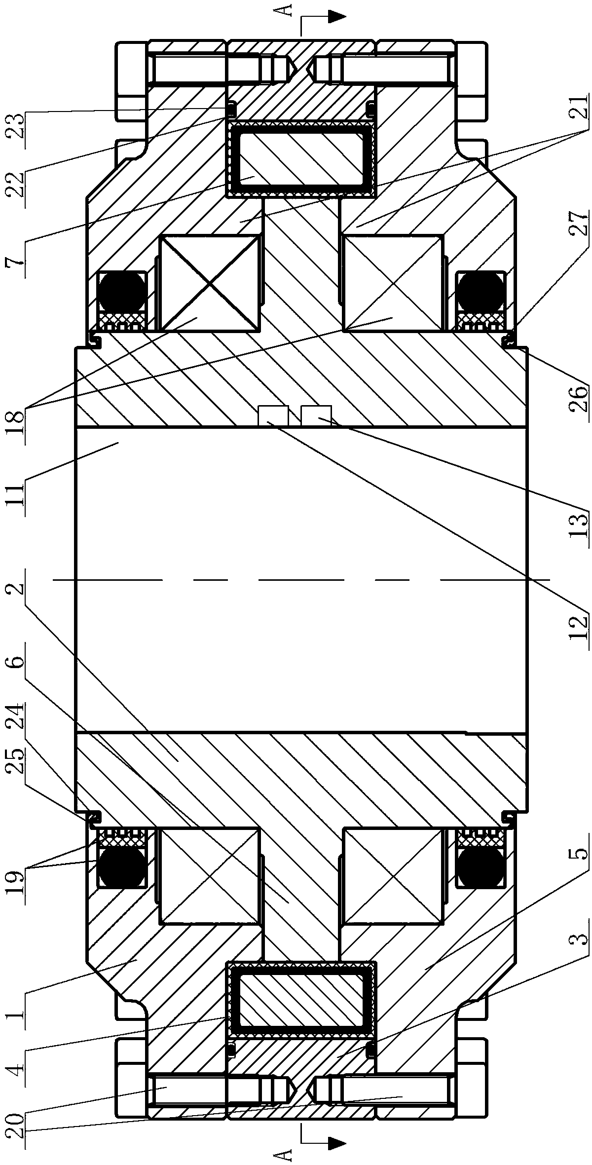
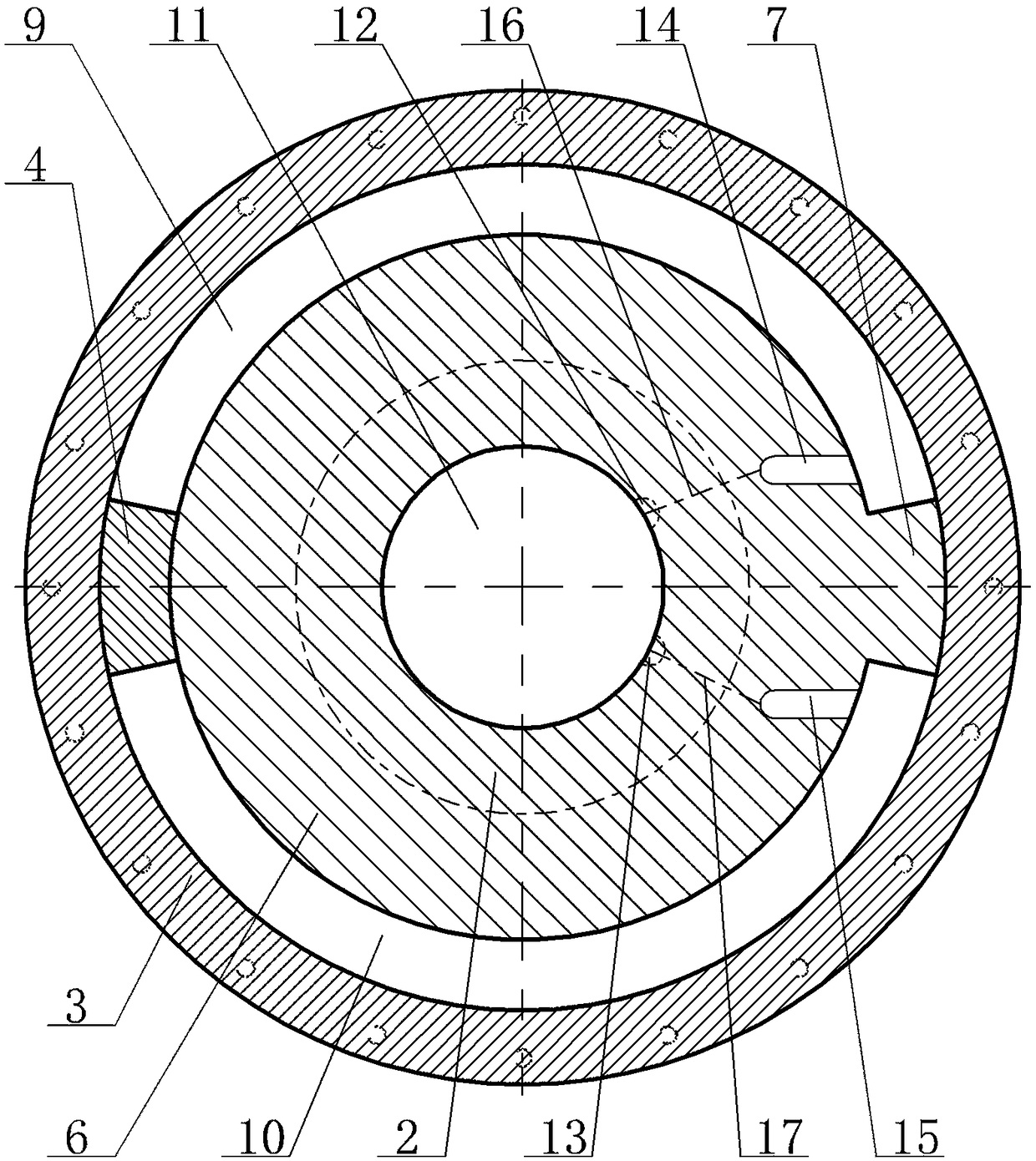
[0017] Special vane swing hydraulic cylinder for robot kinematic joints, see figure 1 , figure 2 : It includes an upper end cover 1, a rotating shaft 2, a cylinder body 3, a stator 4, and a lower end cover 5. The outer ring surface of the axial middle region of the rotating shaft 2 is provided with a side convex ring 6, and the radial direction of the side convex ring 6 is provided with a side The convex blade 7, the side convex blade 7, the side convex ring 6 and the rotating shaft 2 form an integral structure. The upper end cover 1 is set on the rotating shaft 2 and is located on the upper part of the side convex ring 6. The lower end cover 5 is set on the rotating shaft 2 and is located on the side convex ring 6. The lower part of the side convex blade 7 is in the zero state, and the other radial end of the side convex blade 7 is arranged with a fixed piece 4, the inner wall of the fixed piece 4 and the outer wall of the side convex ring 6 are arranged with a gap, and the ...


PUM


Abstract

The invention provides a special blade swinging type hydraulic cylinder for a robot motion joint, and the special blade swinging type hydraulic cylinder can bear large axial force and capsizing moment. A mechanical seal structure is adopted, a dustproof ring is removed, and therefore the special blade swinging type hydraulic cylinder is simple in structure, compact in space layout, reasonable in design, little in inner leakage, large in torque density and convenient to integrate. The special blade swinging type hydraulic cylinder comprises an upper end cover, a rotation shaft, a cylinder body,a fixed sheet and a lower end cover. A side protruding ring is arranged on the outer ring face of the axial middle area of the rotation shaft, and a side protruding blade is arranged on the side protruding ring in the radial direction. An integral structure is integrally formed by the side protruding blade, the side protruding ring and the rotation shaft. The upper end cover sleeves the rotationshaft and is located at the upper portion of the side protruding ring. The lower end cover sleeves the rotation shaft and is located at the lower portion of the side protruding ring. The side protruding blade is in the zero-position state, and the other end opposite to the side protruding blade in the radial direction is provided with the fixed sheet. The inner wall of the fixed sheet and the outer wall of the side protruding ring are arranged in a clearance manner, and a sealing device is arranged in the axial direction of the fixed sheet and the side protruding blade.

Description

technical field [0001] The invention relates to the technical field of a robot shutdown structure, in particular to a blade swing type hydraulic cylinder dedicated to a robot's kinematic joints. Background technique [0002] A robot is a machine device that performs work automatically. It can accept human command, run pre-programmed programs, and act according to principles formulated with artificial intelligence technology. Its mission is to assist or replace human work in jobs such as manufacturing, construction, or hazardous jobs. A robot is generally composed of an actuator, a drive device, a detection device, a control system, and complex machinery, among which the actuator basically uses a servo valve motor plus a harmonic reducer or an RV reducer. Although this structure has been widely used in the field of robotics, it is undeniable that its torque density ratio is relatively low. Due to the characteristics of high power density of hydraulic drive, countries all o...

Claims


Application Information

Patent Timeline
Patent Type & Authority Applications(China)
IPC IPC(8): F15B15/12F15B15/20F16J15/16B25J17/02
CPCF15B15/12B25J17/0258F15B15/20F15B2215/30F16J15/16
Inventor 赵言正
Owner JIANGSU DREAMWELL DYNAMICS TECH CO LTD
Why Eureka
Try Eureka