
Deep well pump with efficient waterproof motor and production technology thereof
A technology for waterproof motors and deep well pumps, which is applied to parts, pumps, pump devices, etc. of pumping devices used for elastic fluids. It can solve problems such as motor damage, prolong service life, reduce the probability of damage, and save costs. Effect
- Summary
- Abstract
- Description
- Claims
- Application Information
AI Technical Summary
Problems solved by technology
Method used
Image

Examples
Embodiment 1
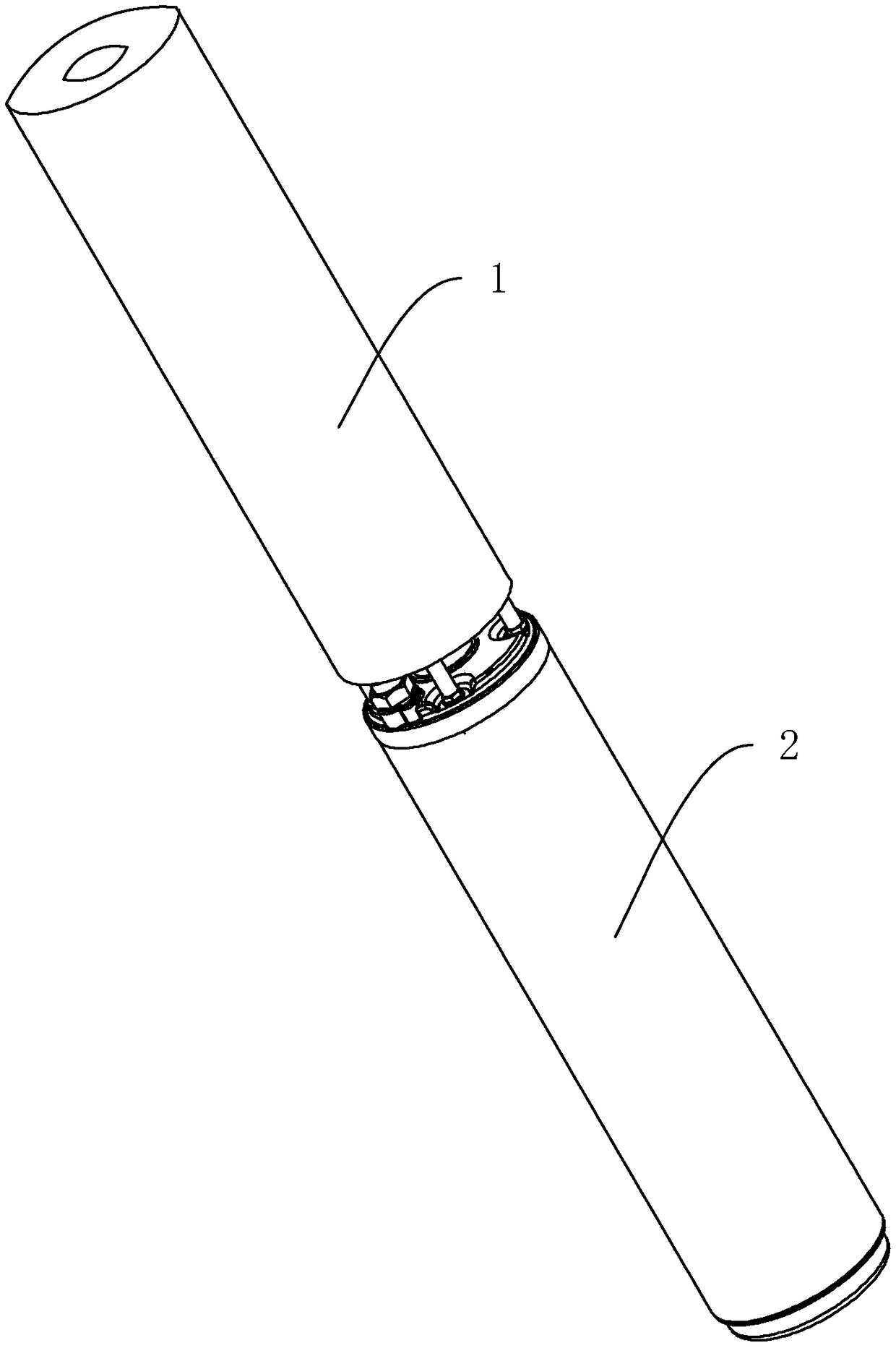
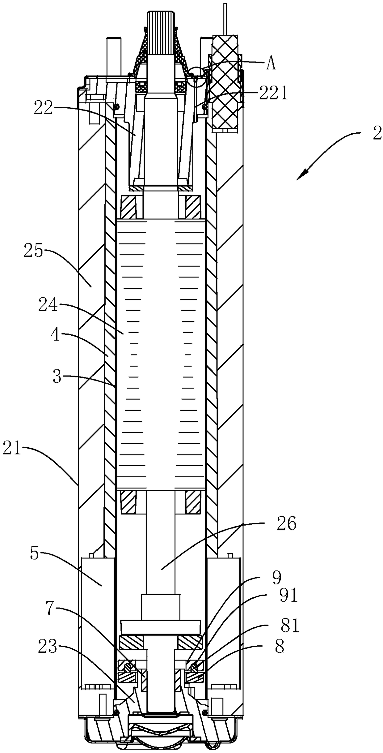
[0044] see figure 1 , figure 2 , a deep well pump with a high-efficiency waterproof motor, including a pump body 1, a motor 2 fixedly connected to the bottom of the pump body 1, the motor 2 includes a barrel 21, a rotor 24 and a stator coil 25 are arranged in the barrel 21, and the stator coil The outer sidewall of 25 is fixedly connected on the inner sidewall of machine barrel 21, and the middle part of rotor 24 along the length direction is pierced with output shaft 26, and the two ends of machine barrel 21 are respectively provided with upper bearing seat 22, lower bearing seat 23, output shaft One end of 26 is connected to the lower bearing seat 23, and the other end passes through the upper bearing seat 22 and is connected to the pump body 1.
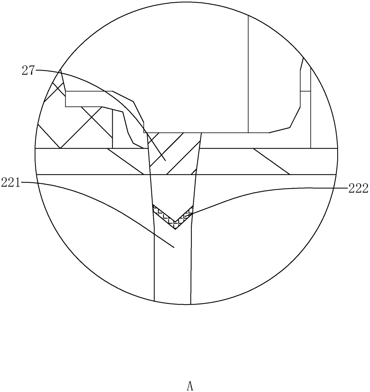
[0045] see figure 2 , image 3 A cylindrical shielding sleeve 3 is provided between the outer wall of the rotor 24 and the stator coil 25. The shielding sleeve 3 is made of stainless steel for isolating the rotor 24 and the st...
Embodiment 2
[0052] A deep well pump production process with a high-efficiency waterproof motor, comprising the following steps:
[0053] Step 1: first install the stator coil 25 into the barrel 21, and put the upper bearing seat 22 into the end of the barrel 21 close to the pump body 1, and then put the shielding sleeve 3 into the barrel 21 so that the shielding sleeve 3 fits On the stator coil 25, put the rotor 24 into the shielding sleeve 3 so that the output shaft 26 protrudes from the end of the upper bearing seat 22, and then put the capacitor 5 on the outside of the shielding sleeve 3 at the bottom of the barrel 21;
[0054] Step 2: The epoxy resin 4 can be poured three times through the pouring hole 6 to the stator coil 25. When pouring for the first time, first vacuum the inside of the machine barrel 21 for the first time, and then fill the ring that needs to be filled for the first time. The epoxy resin 4 is heated to 70-80° C., and the heating time is 15-25 minutes. After the ep...
PUM
 Abstract
Description
Claims
Application Information