Sliding tool
A technology of tools and skateboards, applied in sleds, motor vehicles, transportation and packaging, etc., can solve the problem of single mode
Pending Publication Date: 2018-12-11
SHENZHEN DANMING TECH CO LTD
0 Cites 2 Cited by
AI-Extracted Technical Summary
Problems solved by technology
[0003] Usually, after the sliding tool is assembled, the plane or direction of the running trajectory of the driving end of the driving device driven by the...
Method used
Arranged like this, input-end gear 91 and output-end gear 92 mesh with different intermediate gears respectively, can not interfere, can make kinematic mechanism 10 rotate with respect to main slide part 70 and have larger motion range, make slide tool be Wider adaptability.
Certainly, in practice, also can make the driving end 20a of driving part 20 and the sliding end of main sliding part 70 be parallel to each other, in this state, it can be understood that driving part 20 does not actually play a role in driving main sliding part 70. The effect of sliding, however, the whole sliding tool can rely on inertial sliding, at this time, can reduce sliding resistance; In addition, from this parallel state, there are two included angle directions to choose from to adjust the driving end 20a of the driving part 20 and the main The angle between the sliding ends of the sliding part 70 can play the role of making the sliding tool switch between the forward and reverse driving states (similar to the switching of the forward gear and the reverse gear of the vehicle); The effect of the slide tool going backwards or forwards.
[0142] In addition, the gear assembly of the transmission part of the driving device may only include two parallel intermediate gears 93a, 93b fixedly sleeved on the first rotating shaft 95, and one of the two intermediate gears 93a is connected to the driving source, The other is in drive connection with the motion mechanism 10, that is ...
Abstract
The invention discloses a sliding tool, comprising a main sliding part and a driving device. The driving device comprises a moving mechanism and a driving part connected with the moving mechanism; Thedriving part has a drive end capable of abutting against the ice or snow ground; The moving mechanism can drive the driving end of the driving part to abut and move with ice or snow so as to drive the main sliding part to slide; The relative position between the moving mechanism and the main sliding part can be adjusted so as to adjust the angle between the moving track of the driving end drivenby the moving mechanism and the sliding end of the main coasting part. The relative position between the movement mechanism and the driving part is fixed, so that the moving track of the driving end driven by the moving mechanism and the driving end can be adjusted to be mutually inclined or perpendicular to each other. The sliding mode of the sliding tool is varied, which meets the different needs of actual sliding.
Application Domain
Sledges
Technology Topic
EngineeringMechanical engineering
Image
Examples
- Experimental program(1)
Example Embodiment
[0096] In order to enable those skilled in the art to better understand the solution of the present invention, the present invention will be further described in detail below with reference to the accompanying drawings and specific embodiments.
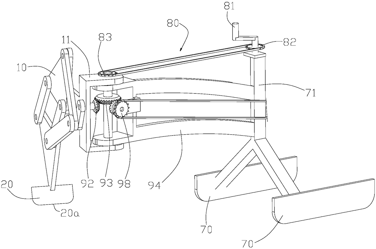
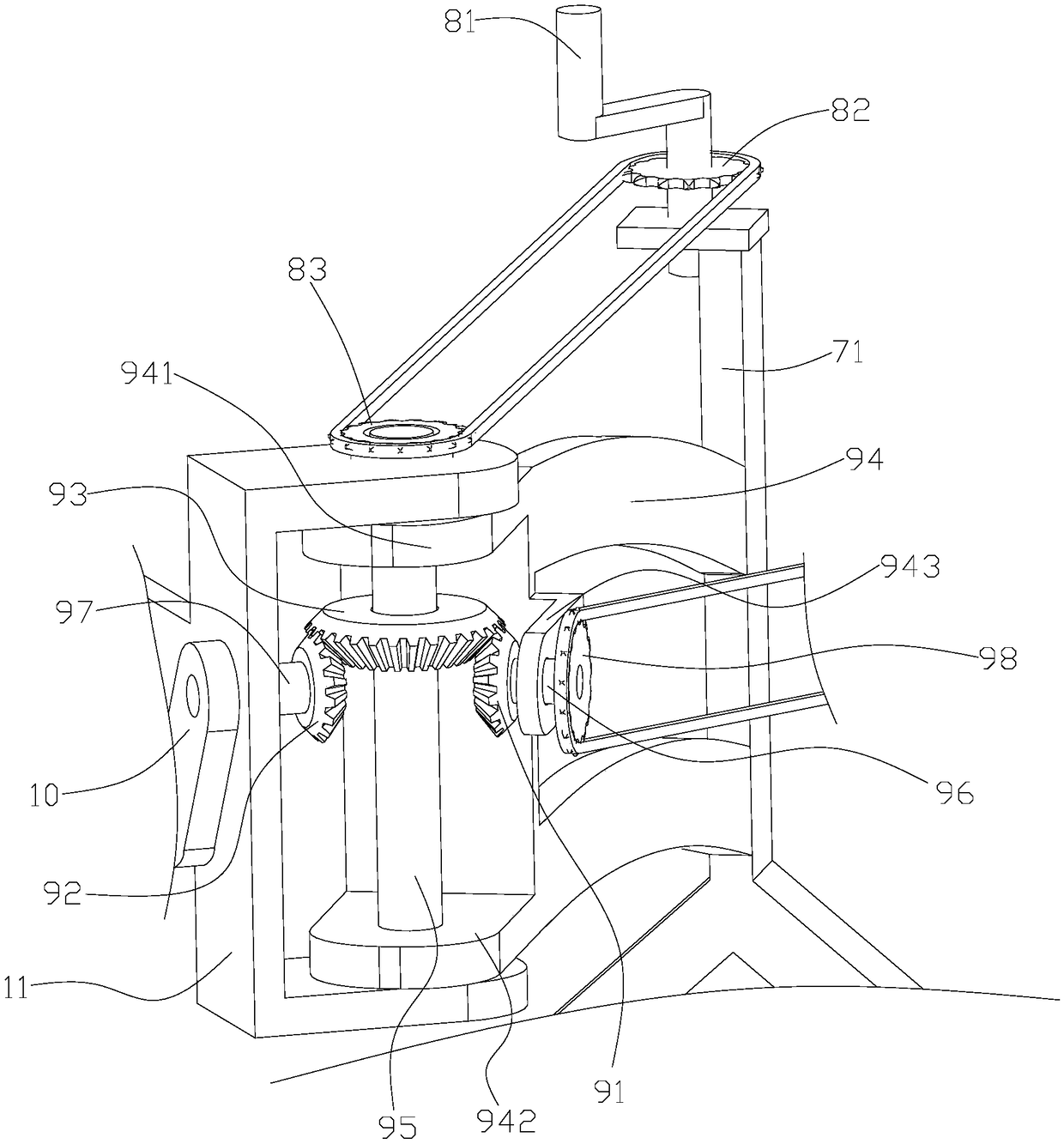
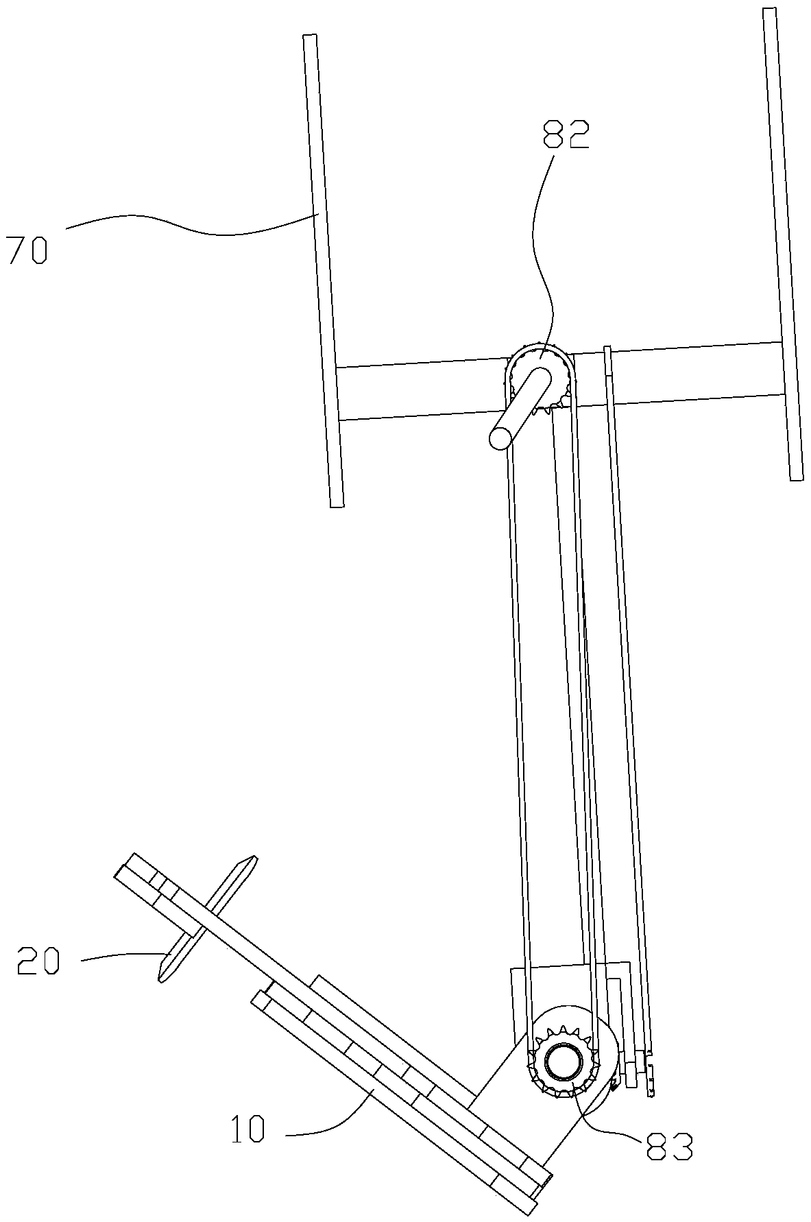
[0097] Please refer to Figure 1 to Figure 3 , figure 1 Is a schematic structural diagram of the first embodiment of the sliding tool provided by the present invention; figure 2 for figure 1 The partial structure diagram of the sliding tool shown at another angle; image 3 for figure 1 The structure diagram of the sliding tool shown from another angle.
[0098] It should be noted that the tilt setting described in this article does not include the situation where the two are perpendicular.
[0099] In this embodiment, the sliding tool includes a main sliding portion 70 and a driving device.
[0100] The driving device includes a motion mechanism 10 and a driving part 20 connected with the motion mechanism 10; the driving part 20 has a driving end 20a that can abut against ice or snow.
[0101] The motion mechanism 10 can drive the driving end 20a of the driving part to abut against ice or snow and move, so as to drive the main sliding part 70 to slide.
[0102] It should also be noted that during the driving process, when the sliding end of the main sliding portion 70 and the motion mechanism 10 drive the driving portion 20 to move in the plane or direction of the trajectory is in a mutually inclined or perpendicular state, and when the driving end 20a and the main sliding When the angle between the sliding ends of the part 70 is inclined, the driving part 20 will slide in the extending direction of the driving end 20a on the ice surface; the main sliding part 70 will slide in the extending direction of the sliding end.
[0103] In a specific solution, the driving portion 20 is a skateboard structure or an ice skate structure, or the driving portion 20 is a structure for mounting rollers.
[0104] Wherein, the relative position between the movement mechanism 10 and the main sliding portion 70 can be adjusted, so as to adjust the angle between the plane or direction of the running track of the movement mechanism 10 driving the driving end 20a and the sliding end of the main sliding portion 70;
[0105] At the same time, the relative position between the motion mechanism 10 and the driving component 20 is fixed, so that the plane or direction of the driving end 20a and the motion mechanism 10 to drive the driving part 20 to move is in a vertical state or in an inclined state with a set angle; or The relative position between the motion mechanism 10 and the driving part 20 can be adjusted, and the angle between the plane or direction of the running track of the motion mechanism 10 driving the driving part 20 and the driving end 20a can be adjusted to be inclined or vertical.
[0106] It can be understood that when the relative position between the motion mechanism 10 and the driving component 20 is fixed, the angular positional relationship between the driving end 20a and the plane or direction of the trajectory of the motion mechanism 10 driving the driving part 20 is fixed and invariable; It can also be understood that when the relative position between the motion mechanism 10 and the driving component 20 can be adjusted, the adjustment process does not exclude the possibility of adjusting the plane or direction of the running track of the motion mechanism 10 to drive the driving part 20 and the driving end 20a. In a parallel state.
[0107] Preferably, the driving end 20a and the plane or direction of the running track of the driving part 20 driven by the motion mechanism 10 are perpendicular to each other.
[0108] Preferably, the plane or direction of the driving end 20a and the running track of the driving part 20 driven by the motion mechanism 10 are perpendicular to each other, and the sliding end of the main sliding part 70 and the plane or direction of the running track of the driving part 20 driven by the motion mechanism 10 are mutually inclined. .
[0109] Preferably, the plane or direction of the driving end 20a and the running track of the driving part 20 driven by the motion mechanism 10 are inclined to each other, and the plane or direction of the sliding end of the main sliding part 70 and the running track of the driving part 20 driven by the motion mechanism 10 are perpendicular to each other. .
[0110] In the sliding tool provided by the present invention, the sliding of the main sliding portion 70 relies on the driving force generated when the driving end 20a moves against ice or snow. The movement of the driving portion 20 with the driving end 20a is determined by the movement mechanism 10. Therefore, the angular position relationship between the driving end 20a and the sliding end of the main sliding part 70, and the plane or direction of the running track of the driving part 20 driven by the motion mechanism 10 is the same as the sliding of the driving end 20a and the main sliding part 70 The angular position relationship between the ends is the main factor that affects the sliding mode of the main sliding portion 70; the relative position between the motion mechanism 10 of the sliding tool and the main sliding portion 70 can be adjusted, so that in actual sliding, it can be adjusted according to the needs of sliding Change the angle between the plane or direction of the driving end 20a and the sliding end of the main sliding portion 70 under the driving of the motion mechanism 10, and/or change the angle between the driving end 20a and the sliding end of the main sliding portion 70, thereby Change the sliding mode to make the sliding tool more adaptable to different working conditions and sliding requirements.
[0111] For example, in the same motion cycle of the motion mechanism 10, the distance that the drive end 20a moves to drive the main sliding part 70 to slide depends on the three (drive end 20a, the sliding end of the main sliding part 70, and the motion mechanism 10 drives the drive part 20 to move). The angle of the plane or direction of the running track is different. The specific performance is: in the same motion cycle of the motion mechanism 10, when the relative position between the motion mechanism 10 and the main sliding part 70 is adjusted to the driving part 20 The angle between the plane or direction of the trajectory driven by the motion mechanism 10 and the sliding end of the main sliding portion 70 is inclined or perpendicular, and the plane or direction of the trajectory of the driving end 20a and the motion mechanism 10 driving the driving portion 20 are perpendicular to each other. Or when tilting, the smaller the angle between the driving end 20a and the sliding end of the main sliding portion 70 is or the more it tends to be parallel (not including parallel), the longer the sliding distance of the main sliding portion 70 is.
[0112] In a specific solution, by adjusting the relative position of the movement mechanism 10 and the main sliding portion 70, the driving end 20a of the driving portion 20 and the sliding end of the main sliding portion 70 can be in a mutually inclined state or a vertical state or a mutually parallel state or change the driving The inclination angle between the end 20a and the sliding end of the main sliding portion 70.
[0113] Here, the driving sliding state refers to a state in which the motion mechanism 10 drives the driving portion 20 to move, and then drives the main sliding portion 70 to slide; relatively, there is a freewheeling state when the motion mechanism 10 is not operating.
[0114] In order to achieve the speed change effect, the driving end 20a of the driving part 20 and the sliding end of the main sliding part 70 can be arranged to be inclined to each other by adjustment. In the driving sliding state, the angle between the two determines the degree of speed change.
[0115] Of course, in practice, the driving end 20a of the driving part 20 and the sliding end of the main sliding part 70 can also be made parallel to each other. In this state, it can be understood that the driving part 20 does not actually serve to drive the main sliding part 70 to slide. However, the entire sliding tool can slide by inertia, at this time, the sliding resistance can be reduced; in addition, from the parallel state, there are two angle directions to choose from to adjust the driving end 20a of the driving part 20 and the main sliding part 70 The angle between the sliding ends of the sliding tool can switch between the driving state of the sliding tool in forward or reverse (similar to the switching of the forward gear and the reverse gear of the vehicle); it can play the role of reversing the sliding tool during the driving process Or forward role.
[0116] In practice, it is also possible to make the driving end 20a of the driving part 20 and the plane or direction of the driving part 20 driven by the motion mechanism 10 perpendicular to each other, and the plane or direction of the driving part 20 driven by the motion mechanism 10 and the direction The sliding ends of the main sliding portion 70 are parallel to each other.
[0117] In a specific solution, the movement mechanism 10 can be rotatably connected with the main sliding portion 70, and the positional relationship between the two can be adjusted by rotation. Of course, it can be understood that, in addition to rotation, other connection methods can also be selected to realize the position adjustment of the two.
[0118] Specifically, the motion mechanism 10 includes a frame 11, the main sliding portion 70 includes a bracket 71, and the frame 11 and the bracket 71 are rotationally connected through a first rotating shaft 95 to realize the rotational connection between the motion mechanism 10 and the main sliding portion 70.
[0119] Specifically, a supporting frame 94 is fixed to the bracket 71, the first rotating shaft 95 passes through the corresponding mounting holes on the supporting frame 94 and the frame 11, and both the supporting frame 94 and the frame 11 are rotatably connected with the first rotating shaft 95.
[0120] In order to facilitate adjustment of the relative position between the movement mechanism 10 and the main sliding portion 70, the sliding tool may also be provided with a driving member 80 for driving the frame 11 to rotate relative to the bracket 71.
[0121] In a specific solution, the driving component 80 includes a handle 81, a first driving wheel 82 fixed to the handle 81, a first driven wheel 83, and a belt or chain tensioned on the first driving wheel 82 and the first driven wheel 83 (Figure Not marked in).
[0122] Wherein, the handle 81 and the first driving wheel 82 can be fixed by a fixed shaft, which is rotatably connected to the bracket 71 of the main sliding portion 70, that is, when the handle 81 is rotated, the first driving wheel 82 can be driven relative to the bracket 71 Rotation; Among them, the first driven wheel 83 is fixed to the frame 11 connected to the movement mechanism 10, and the first driven wheel 83 and the first rotating shaft 95 are coaxially arranged.
[0123] In this way, by rotating the handle 81, the first driving wheel 82 rotates synchronously, and the second driven wheel 83 is driven to rotate through the belt or chain transmission, thereby driving the movement mechanism 10 to rotate around the first rotating shaft 95, thereby changing the movement mechanism 10 and the main sliding part 70 , And the relative positional relationship between the driving part 20 connected to the motion mechanism 10 and the main sliding part 70, which also changes the angle between the driving end 20a of the driving part 20 and the sliding end of the main sliding part 70, and the driving end 20a The angle between the plane or direction of the running track driven by the motion mechanism 10 and the sliding end of the main sliding portion 70.
[0124] It should be noted that in practice, the handle 81 is not provided, and it is also feasible to directly rotate the first driving wheel 82 with the bracket 71, but relatively speaking, the operation is not as convenient as the handle 81.
[0125] In a specific solution, the driving device further includes a driving source and a transmission component, wherein the transmission component is connected between the driving source and the movement mechanism 10.
[0126] Specifically, the transmission component includes a second driving wheel (not shown in the figure) connected with the driving source, a second driven wheel 98, and a belt or chain tensioned on the second driving wheel and the second driven wheel 98.
[0127] Transmission components also include gear components, such as figure 1 with figure 2 As shown, in this solution, the gear assembly includes an input end gear 91, an intermediate gear 93 and an output end gear 92; wherein the input end gear 91 is fixedly connected to the second driven wheel 98, and the output end gear 92 is fixedly connected to the motion mechanism 10. , Both the input gear 91 and the output gear 92 mesh with the intermediate gear 93.
[0128] During operation, the second driving wheel is driven to rotate by the drive source, and the second driven wheel 98 is driven to rotate through the belt or chain transmission. Because the input gear 91 is fixed to the second driven wheel 98, the second driven wheel 98 is driven synchronously when rotating The input gear 91 rotates, and the input gear 91 drives the output gear 92 to rotate through the intermediate gear 93, thereby driving the movement mechanism 10 to move.
[0129] In this solution, the motion mechanism 10 is specifically in the form of a link structure, and the links of the motion mechanism 10 act on each other, and finally drive the driving part 20 to act.
[0130] As shown in the figure, specifically, the transmission component further includes a support frame 94, the first end of the support frame 94 is fixedly connected to the bracket 71 of the main sliding portion 70, and the second end is rotatably connected to the frame 11 of the motion mechanism 10.
[0131] Specifically, the second end of the support frame 94 includes an upper ear plate 941 and a lower ear plate 942, the positions of which correspond up and down, and a rotatable first shaft 95 is inserted between the upper ear plate 941 and the lower ear plate 942, That is to say, the first rotating shaft 95 can rotate relative to the supporting frame 94, wherein the intermediate gear 93 is sleeved on the first rotating shaft 95. When specifically arranged, the intermediate gear 93 can be relatively fixed to the first rotating shaft 95 or relative to the first rotating shaft. 95 turns.
[0132] A bending plate 943 is also provided between the upper ear plate 941 and the lower ear plate 942. A rotatable second rotating shaft 96 is inserted into the bending plate 943. One end of the second rotating shaft 96 is fixed to the second driven wheel 98. The other end is fixedly connected to the input gear 91.
[0133] Specifically, a rotatable third rotating shaft 97 is inserted into the frame 11 of the motion mechanism 10, one end of the third rotating shaft 97 is fixedly connected to the input end connecting rod of the motion mechanism 10, and the other end is fixedly connected to the output end gear 92.
[0134] Among them, the input gear 91, the output gear 92, and the intermediate gear 93 are all bevel gears. Of course, they can also be gears of other forms as long as power transmission can be achieved.
[0135] It can be understood that the above is only a specific embodiment of the transmission component. In practice, the transmission component provided between the driving source and the motion mechanism 10 can have various forms, and other changes can be made on the basis of the above specific embodiment.
[0136] In this solution, since there is only one intermediate gear 93, both the input gear 91 and the output gear 92 mesh with the intermediate gear 93. The meshing range of the input gear 91 and the output gear 92 with the intermediate gear 93 is restricted, and the movement The movement range of the mechanism 10 relative to the main sliding portion 70 constitutes a certain degree of restriction.
[0137] In order to avoid the above situation, the above gear assembly can be improved. Please refer to Figure 4 , Figure 4 It is a partial structural diagram of the second embodiment of the sliding tool provided by the present invention.
[0138] Compared with the foregoing embodiment, the difference of this embodiment is only that the gear assembly is improved, and the other basic structure remains unchanged.
[0139] In this embodiment, the gear assembly includes an input gear 91, an output gear 92, and two intermediate gears 93a, 93b.
[0140] As shown in the figure, two intermediate gears 93a, 93b are fixedly sleeved on the first shaft 95 up and down, wherein the input gear 91 meshes with the intermediate gear 93a, and the output gear 92 meshes with the intermediate gear 93b because the two intermediate gears 93a, 93b mesh with each other. 93b is fixedly sleeved on the first rotating shaft 95. While the input gear 91 drives the intermediate gear 93a to rotate, the intermediate gear 93b and the first rotating shaft 95 also rotate together, thereby driving the output gear 92 to rotate, which in turn drives the motion mechanism 10 to move.
[0141] With this arrangement, the input gear 91 and the output gear 92 respectively mesh with different intermediate gears without interference. The movement mechanism 10 can rotate with respect to the main sliding portion 70 to have a larger range of motion, making the sliding tool more adaptable. wide.
[0142] In addition, the gear assembly of the transmission component of the driving device may also only include two parallelly arranged intermediate gears 93a, 93b fixedly sleeved on the first rotating shaft 95. One of the two intermediate gears 93a is connected to the driving source and the other It is in transmission connection with the movement mechanism 10, that is, the driving source directly drives the intermediate gear 93a or 93b to move, so that the second driving wheel, the second driven wheel 98 and the belt or chain tensioned between the two in the aforementioned solution can be omitted, And the input end gear 91; this arrangement can reduce the number of parts and make the structure of the drive device more compact.
[0143] It can be understood that the transmission components of the drive device may only include the aforementioned output gear 92 during actual installation. If the structural space and actual conditions permit, the drive source can be directly connected to the output gear 92 in transmission.
[0144] Above figure 1 In the first embodiment shown, the motion mechanism 10 and the driving part 20 are relatively fixed. In actual installation, the position between the motion mechanism 10 and the driving part 20 can also be set to a structure that can be adjusted relatively. The motion mechanism 10 drives the angle between the plane or direction of the driving end 20a and the driving end 20a, and/or adjusts the angle between the driving end 20a and the sliding end of the main sliding portion 70.
[0145] That is, in order to adjust the angle between the plane or direction of the running track of the driving end 20a driven by the motion mechanism 10 and the sliding end of the main sliding portion 70, and/or to adjust the sliding of the driving end 20a and the main sliding portion 70 The angle between the ends can be adjusted to the relative position between the motion mechanism 10 and the main sliding portion 70. The specific form is as described above, and the relative position between the motion mechanism 10 and the driving portion 20 can also be set as Adjustable state, or set the above-mentioned motion mechanism 10 and the main sliding portion 70, as well as the motion mechanism 10 and the driving portion 20 to the angular position adjustable state.
[0146] The embodiments in which the relative angular position between the movement mechanism 10 and the main sliding portion 70 are adjustable have been described in detail above, and the realization of the adjustment in the relative position between the movement mechanism 10 and the driving portion 20 will be described below.
[0147] Please refer to Figure 18 with Figure 19 In a specific solution, the driving part 20 and the motion mechanism 10 are also rotationally connected, and the connecting post 21 of the driving part 20 is inserted into the connecting tube 103 of the motion mechanism 10, and the motion mechanism 10 and the driving mechanism can be adjusted by mutual rotation. The relative position between the parts 20, and then adjust the angle between the driving end 20a and the sliding end of the main sliding part 70; the connecting pipe 103 and the connecting column 21 can adopt a clearance fit or other fixing method, for example, the connecting pipe Screw holes are provided on the pipe wall of 103, and the connecting pipe 103 and the connecting post 21 are fixed by means of top screws.
[0148] In a specific solution, the driving part 20 is a structure in which a roller is installed, the bottom end of the roller is the driving end 20a, and the rolling direction of the roller is the driving end direction or the driving end extension direction.
[0149] In order to achieve the speed change effect, when the angle between the plane or direction of the running track of the motion mechanism 10 driving the drive end 20a and the sliding end of the main sliding portion 70 is vertical or inclined, the motion mechanism 10 drives the running track of the drive end 20a. The angle between the plane or direction and the driving end 20a is vertical or inclined. The angle between the driving end 20a of the driving part 20 and the sliding end of the main sliding part 70 can be adjusted by adjusting. In the driving sliding state, between the two The included angle determines the degree of shifting.
[0150] When the sliding tool slides by inertia, if the angle between the driving end 20a and the sliding end of the main sliding portion 70 is adjusted to a parallel state, the sliding resistance can be reduced.
[0151] Please refer to Figure 5 , Figure 5 for figure 1 A schematic structural diagram of the first specific embodiment of the main sliding portion of the sliding tool shown.
[0152] In this embodiment, the main sliding portion 70 is specifically in the shape of a plate or ice blade, which is fixed to the bracket 71. The sliding end of the main sliding portion 70 includes a first sliding end section 70a and a second sliding end section 70b. A sliding end section 70a transitions with the side surface of the main sliding portion 70 at right angles, acute angles or obtuse angles, and the second sliding end section 70b transitions with the side surface of the main sliding portion 70 with rounded corners. With this arrangement, the second sliding end section 70b has a small lateral sliding resistance, and the first sliding end section 70a has a large lateral sliding resistance. When turning, the first sliding end section 70a is the center of the circle, which is convenient for turning.
[0153] In a specific solution, the first sliding end section 70a is located at the rear of the main sliding section 70, and the second sliding end section 70b is located at the front of the main sliding section 70, so that the sliding tool has low steering resistance when turning.
[0154] Preferably, the front end surface of the main sliding portion 70 is rounded.
[0155] Of course, in actual installation, the first sliding end section 70a may also be located at the front or middle position, and the remaining positions are the second sliding end section 70b.
[0156] Specifically, the length of the first sliding end section 70a is set to be shorter, and the length of the second sliding end section 70b is set to be longer, and the ratio of the two may be determined according to actual requirements.
[0157] It should be noted that the front and back here are defined based on the sliding direction of the main sliding portion 70, and the directional terms related to the front and rear are also defined based on the sliding direction of the main sliding portion 70, and will not be repeated.
[0158] Please refer to Image 6 , Image 6 It is a schematic structural diagram of a second specific embodiment of the main sliding part of the sliding tool provided by the present invention.
[0159] In this embodiment, the main sliding portion 70 also has a plate-like structure or ice skate shape.
[0160] In this embodiment, both sides of the main sliding portion 70 are fixedly connected with lateral sliding plates 72, and the lateral sliding plates 72 are inclined outward. Of course, the lateral sliding plate 72 may be fixed to only one side of the main sliding portion 70.
[0161] Further, the sliding end of the lateral sliding plate 72 is not higher than the sliding end of the main sliding portion 70. With this arrangement, the lateral sliding plate 72 can better function as a steering center during turning to prevent side sliding.
[0162] Furthermore, the lateral sliding plate 72 is arranged close to the rear end of the main sliding portion 70. In this way, when the sliding tool turns, it is helpful to reduce the steering resistance. Of course, it is also feasible to arrange the lateral sliding plate 72 close to the front end or the middle position of the main sliding portion 70.
[0163] Preferably, the sliding end of the main sliding portion 70 and the side surface of the main sliding portion 70 are rounded, and the lateral sliding plate 72 can function as the center of rotation when turning.
[0164] Specifically, the structural design of the sliding end of the main sliding portion 70 may be similar to the first embodiment of the above-mentioned main sliding portion 70 to further reduce the sliding resistance of steering, which is not repeated here.
[0165] In a specific solution, the lateral sliding plate 72 can be made of a material with certain elasticity. When turning, if the sliding end of the lateral sliding plate 72 is against the ice or snow, because of its elasticity, the lateral sliding plate The sliding end of 72 will move downward to increase the lateral sliding resistance, which can prevent side sliding, or it can turn the sliding end of the lateral sliding plate 72 as the center of the circle when turning.
[0166] Please refer to Figure 7 with Figure 8 , Figure 7 It is a schematic structural diagram of a third specific embodiment of the main sliding part of the sliding tool provided by the present invention; Figure 8 for Figure 7 Shown is a schematic diagram of another angle of the main sliding section.
[0167] In this embodiment, the main sliding portion 70 is also a plate-like structure or ice skate shape, and side sliding plates 72 are also provided on both sides of the main sliding portion 70. The difference from the foregoing second embodiment is that the lateral sliding The plate 72 is rotatably connected with the main sliding portion 70 to enable the sliding surface of the lateral sliding plate 72 to move up and down or to adjust the pressure between the sliding surface of the lateral sliding plate 72 and the ice surface or snow; when the main sliding portion 70 slides sideways When the time, the sliding end of the lateral sliding board 72 will be against the ice surface, and the sliding end of the lateral sliding board can move downwards, and the resistance to the ice or snow is greater, which can prevent side sliding or steering When the rotation center deviates. Specifically, such as Figure 7 with Figure 8 As shown, at the rear end of the side surface of the main sliding portion 70, two oppositely positioned supports 73 are provided. The two supports 73 are rotatably inserted with a rotating shaft 74, and the lateral sliding plate 72 is fixedly connected to the rotating shaft 74. , The lateral sliding plate 72 can approach the main sliding portion 70 or away from the main sliding portion 70 with the rotation of the rotating shaft 74, thereby adjusting the angle of the lateral sliding plate 72 to the outside, that is, changing the relative sliding end of the lateral sliding plate 72 The vertical position of the main sliding portion 70.
[0168] It can be understood that in actual sliding, the adjustment of the degree of outward inclination of the lateral sliding plate 72 is passive adjustment. After the lateral sliding plate 72 abuts against the ice or snow, according to the steering situation, the lateral sliding plate 72 can be affected by the resistance. The sliding plate 72 is passively rotated to meet different steering requirements.
[0169] It should be pointed out that, in the solution shown in the figure, the lateral sliding plate 72 is provided at the rear end of the main sliding portion 70, but in practice, it may also be at the front, middle or other positions. In actual installation, the lateral sliding plate 72 may be provided only on one side of the main sliding portion 70.
[0170] In a specific solution, an elastic member 76 is provided between the lateral sliding plate 72 and the main sliding portion 70, so that the angle between the lateral sliding plate 72 and the main sliding portion 70 is maintained at a preset angle or the main sliding portion 70 The sliding surface is pressed against the ice or snow.
[0171] It can be understood that the preset angle enables the lateral sliding plate 72 to function well when the sliding tool is turned, and its specific setting value is set according to the structure of the sliding tool and actual operating requirements. During the sliding process, after the lateral sliding plate 72 rotates relative to the main sliding portion 70, the elastic member 76 also has the function of resetting the lateral sliding plate 72, or gives the sliding surface of the lateral sliding plate 72 a pressing surface or The power of the snow.
[0172] Specifically, the elastic member 76 may be a torsion spring, which has a simple structure and reliable use.
[0173] In a specific solution, a limit member 75 is further provided between the lateral sliding plate 72 and the main sliding portion 70 to limit the angle of the lateral sliding plate 72 to rotate inward, that is, to restrict the lateral sliding plate 72 from approaching the main sliding portion. The angle of rotation 70 is to prevent the lateral sliding plate 72 from rotating to a position parallel to the main sliding portion 70, which cannot play a corresponding role.
[0174] Such as Figure 8 As shown, specifically, the limiting member 75 may be a stopper arranged on the inner side of the support 73. When the lateral sliding plate 72 rotates inward and interferes with the stopper, it cannot continue to rotate inward.
[0175] In the above embodiments of the main sliding portion 70 with the lateral sliding plate 72, the lateral sliding plates 72 are provided on both sides of the main sliding portion 70. It can be understood that, in actual installation, only the main sliding portion 70 It is also feasible to provide a lateral sliding plate 72 on one side.
[0176] Preferably, in the above-mentioned embodiments of the main sliding portion 70 with the lateral sliding plate 72, the sliding end of the lateral sliding plate 72 and the front and/or rear end of the lateral sliding plate 72 are rounded to reduce The sliding resistance of the small lateral sliding plate 72 forward or backward.
[0177] Preferably, in the above-mentioned embodiments of the main sliding portion 70 with the lateral sliding plate 72, the sliding end surface of the lateral sliding plate 72 is an inner concave surface 721, which can be referred to Picture 9 It is understood that with such a setting, the resistance to sliding sideways is large, so that the sliding tool is not easy to slip laterally, and if it encounters a person, the body is less injured.
[0178] In the above-mentioned embodiments, the main body of the main sliding portion 70 has a plate-like structure or an ice skate shape. It can be understood that the main sliding portion 70 may also be provided with wheels in actual installation.
[0179] In addition to the main sliding part 70, the sliding tool may also be provided with a steering sliding plate 100 located in front of the main sliding part 70. Generally, the steering sliding plate 100 is rotatably connected to the main frame of the sliding tool through a steering shaft 101.
[0180] Further, the steering shaft 101 is approximately located in the middle of the steering sliding plate 100, that is, the steering axis of the steering sliding plate 100 is located in the middle.
[0181] reference Picture 10 , Picture 10 It is a schematic diagram of the structure of the steering sliding board in the specific embodiment.
[0182] In a specific solution, part of the section 100a of the sliding end of the steering sliding board 100 transitions with the side of the steering sliding board 100 at a right angle or an acute angle or an obtuse angle, and the remaining sections transition with the side of the steering sliding board 100 with rounded corners. The gliding end section of the transition at an acute or obtuse angle is equivalent to being arranged close to the steering axis of the steering gliding plate 100, that is, roughly located below the steering shaft 101. In the solution shown in the figure, the partial section 100a is located at the middle position of the sliding end of the steering sliding plate 100. In actual installation, the partial section 100a may also be located forward or backward or other positions.
[0183] reference Picture 11 Further, on one or both sides of the steering sliding plate 100, a side sliding plate 102 inclined to the outside may also be provided.
[0184] Further, the sliding end of the side sliding board 102 is not higher than the sliding end 41 of the steering sliding board 100.
[0185] Further, the side sliding board 102 is disposed close to the middle of the steering sliding board 100, that is, the side sliding board 102 is located substantially below the steering shaft 101.
[0186] Further, the side sliding board 102 can also be arranged in a rotational connection with the steering sliding board 100, and the specific manner can be the same as the above-mentioned lateral sliding board 72 and the main sliding portion 70, and the other arrangements can also be arranged similarly.
[0187] Please refer to Picture 12 with Figure 13 , Picture 12 for figure 1 The structure diagram of the sliding tool shown from another angle; Figure 13 for Picture 12 The structure diagram of the movement mechanism shown in another angle.
[0188] Picture 12 with Figure 13 A specific embodiment in which the movement mechanism 10 is in the form of a link is shown in the figure. It is understood that the movement mechanism 10 can be used in combination with the main sliding portion 70 and related components in any of the foregoing embodiments.
[0189] In the solution shown in the figure, the frame 11 of the motion mechanism 10 is generally a flat T-shaped structure, and specifically includes a vertical plate 111 and a horizontal plate 112 connected to the vertical plate 111, wherein the two ends of the vertical plate 111 are bent to the same side to form The upper ear plate 941 and the lower ear plate 942 of the aforementioned support frame 94 respectively cooperate with the two folded plates. Specifically, the first rotating shaft 95 passes through the upper folded plate, the upper ear plate 941, and the lower ear plate 942 in sequence. The frame 11 and the support frame 94 are rotatably connected with the folded plate on the lower side.
[0190] The main body of the link structure of the motion mechanism 10 includes a first link 12, a second link 13, a third link 14, a fourth link 15, a fifth link 16, a sixth link 17 and a seventh link 18. ; Among them, the fourth link 15 and the seventh link 18 are triangular structures.
[0191] Wherein, one end of the first link 12 is rotatably connected with the vertical plate 111 of the frame 11. Specifically, one end of the first link 12 is rotatably connected with the vertical plate 111 through the aforementioned third shaft 97, that is, the third shaft 97 One end of is fixed to the first connecting rod 12. When power is transmitted to the output gear 92 fixed to the third rotating shaft 97, the third rotating shaft 97 is driven to rotate, and the first connecting rod 12 is driven to rotate, thereby driving the entire Link structure action.
[0192] One end of the second link 13 and the third link 14 are both rotatably connected with the other end of the first link 12, and the other end of the second link 13 is rotatably connected with a corner of the fourth link 15, and the fourth link 15 The other two corners of the fifth link 16 and one end of the sixth link 17 are respectively rotatably connected, and the other end of the fifth link 16 and the other end of the sixth link 17 are respectively connected to the seventh link 18 The two corners are rotationally connected, and the third corner of the seventh connecting rod 18 is fixedly connected to the driving part 20.
[0193] The other end of the third link 14 is rotationally connected to a corner of the seventh link 18, and its rotational connection center is the same as the rotational connection center of the sixth link 17 and the seventh link 18, that is, the third link 14 The sixth link 17 and the seventh link 18 are rotationally connected at the same position.
[0194] At the same time, the end of the horizontal plate 112 is also rotatably connected with the rotational connection point of the fourth link 15 and the sixth link 17.
[0195] After the above setting, the driving source is transmitted to the third rotating shaft 97 fixedly connected to the first connecting rod 12 through the transmission component. The first connecting rod 12 rotates around the axis of the third rotating shaft 97, and the motion track at the other end is circular. During the rotation of the first connecting rod 12, the second connecting rod 13 and the third connecting rod 14 connected to it are driven to move. It can be understood that because the fourth connecting rod 15 is also rotatably connected with the horizontal plate 112 of the frame 11, During the action of the lever structure, the position of the corner portion of the fourth link 15 that is rotationally connected to the horizontal plate 112 remains unchanged; driven by the link structure, the driving part 20 realizes the movement in the forward and backward directions and up and down directions.
[0196] Picture 12 with Figure 13 A specific implementation form of the motion mechanism 10 is exemplarily given. It can be understood that, in actual installation, the connecting rod structure may also be in other forms, and is not limited to what is shown in the figure.
[0197] In the foregoing embodiments, the motion mechanism 10 is specifically in the form of a link structure. It can be understood that the structure of the motion mechanism 10 is not limited to a link structure. For example, it may also be a belt drive structure or other structural forms, as long as it can drive The movement of the driving part 20 can realize the driving of the main sliding part 70.
[0198] Please refer to Figure 14 with Figure 15 , Figure 14 A schematic structural diagram of a third embodiment of a sliding tool provided by the present invention, Figure 15 for Figure 14 Another view of the structure of the sliding tool is shown, in which the structure of the main sliding part is omitted.
[0199] With the aforementioned Figure 1-3 Compared with the illustrated embodiment, the main difference of this embodiment is that the driving component 80 is eliminated, and the main body of the movement mechanism 10 is a belt drive structure.
[0200] Such as Figure 14 As shown, the rotational connection between the frame 11 of the motion mechanism 10 and the bracket 71 of the main sliding portion 70 is the same as that described in the foregoing embodiment.
[0201] The bracket 71 is also fixedly connected to a supporting frame 94, the first end of the supporting frame 94 is fixed to the bracket 71, and the second end is rotatably connected to the frame 11 through the first rotating shaft 95.
[0202] The frame 11 also has a bolt hole corresponding to the bolt 110. After adjusting the position, the bolt 110 can be screwed into the bolt hole until the bolt 110 is pressed against the support frame 94, thereby defining the movement mechanism 10 and the main sliding part The relative position between 70.
[0203] In this way, before each sliding, the frame 11 or the supporting frame 94 can be manually rotated to rotate around the first rotating shaft 95 to adjust the relative position between the main sliding portion 70 and the motion mechanism 10. After the adjustment, use bolts 110 is positioned to prevent the relative position of the main sliding portion 70 and the motion mechanism 10 from changing during the sliding process.
[0204] In this embodiment, the main body of the movement mechanism 10 is a belt transmission structure, specifically as Figure 15 As shown, it includes two pulleys and a belt tensioned between the two pulleys. Among them, one pulley is connected to the driving source as the main pulley 191, the other pulley is the driven pulley 192, and the driving part 20 is connected to the belt. In the process of belt drive, it moves in the front and rear direction or in the front and back direction and up and down direction.
[0205] In the scheme shown in the figure, the drive source and the transmission components connected between the drive source and the belt transmission structure are the same as those described in the foregoing first embodiment, and will not be repeated here. It can be understood that the transmission components can also be as many as described above. Kind of transformation.
[0206] Such as Figure 15 As shown, the two pulleys are respectively rotatably connected to the two ends of the frame 11 through a rotating shaft. Of course, the above-mentioned output gear 92 is fixedly mounted on the rotating shaft of the main pulley 191, so that the power transmitted by the output gear 92 Rotate.
[0207] In the above embodiments, the relative position between the movement mechanism 10 and the main sliding portion 70 can be adjusted. In actual installation, the relative position between the movement mechanism 10 and the main sliding portion 70 may also be fixed.
[0208] Please refer to Figure 16 , Figure 16 It is a schematic structural diagram of the fourth embodiment of the sliding tool provided by the present invention.
[0209] The sliding tool includes a main sliding portion 70 and a driving device, wherein the driving device includes a movement mechanism 10 and a driving portion 20 connected to the movement mechanism 10, and the driving portion 20 has a driving end 20a capable of abutting against ice or snow.
[0210] The movement mechanism 10 can drive the driving end 20a to abut against ice or snow and move, so as to drive the main sliding portion 70 to slide.
[0211] In this embodiment, the position between the movement mechanism 10 and the main sliding portion 70 is relatively fixed, and is configured such that the extending direction of the driving end 20a is inclined to the sliding end of the main sliding portion 70, and the movement mechanism 10 drives the driving portion 20 to move. The plane or direction of the running track and the sliding end of the main sliding portion 70 are inclined to each other.
[0212] The plane or direction of the driving end 20a and the running track of the driving part 20 driven by the motion mechanism 10 are inclined or perpendicular to each other.
[0213] Preferably, the driving end 20a and the plane or direction of the running track of the driving part 20 driven by the motion mechanism 10 are perpendicular to each other.
[0214] Wherein, the main structure setting mode of the main sliding portion 70 can be any of the aforementioned embodiments, and will not be repeated here.
[0215] In the solution shown in the figure, the movement mechanism 10 is specifically a belt transmission structure. The movement mechanism 10 and the main sliding portion 70 are connected by a connecting rod 120. One end of the connecting rod 120 is fixedly connected with the main sliding portion 70, and the other end is fixed on the movement mechanism 10. The parts that do not change.
[0216] The connecting rod 120 has a bent structure and includes two sections. The first connecting rod section is fixedly connected to the bracket of the main sliding portion 70, and the first connecting rod section and the sliding end of the main sliding portion 70 are parallel to each other, and the second connecting rod The rod section and the first connecting rod section have a certain inclination angle, the second connecting rod section is fixed to the motion mechanism 10, and the plane or direction of the trajectory of the second connecting rod section and the motion mechanism 10 driving the driving part 20 is mutually Vertically, after this arrangement, the sliding end of the main sliding portion 70 is parallel to the running track of the driving portion 20 driven by the motion mechanism 10 and is inclined to each other, and the degree of inclination is the same as that between the second connecting rod section and the first connecting rod section. The inclination angle of is related, and can be determined according to actual needs.
[0217] Please refer to Figure 17 , Figure 17 It is a schematic structural diagram of the fifth embodiment of the sliding tool provided by the present invention.
[0218] With the aforementioned Figure 16 Compared with the illustrated embodiment, the difference of this embodiment is that the plane or direction of the running track of the motion mechanism 10 driving the driving part 20 is perpendicular to the sliding end of the main sliding part 70, and the driving end 20a and the motion mechanism 10 drive the drive. The planes or directions of the trajectories of the movement of the parts 20 are mutually inclined.
[0219] Such as Figure 17 As shown, the movement mechanism 10 and the main sliding portion 70 are also connected by a connecting rod 120' to define the relative position between the two.
[0220] Wherein, the connecting rod 120' has a linear structure, one end of the connecting rod 120' is fixedly connected to the bracket of the main sliding portion 70, and its extending direction is parallel to the sliding end of the main sliding portion 70, and the other end of the connecting rod 120' is fixedly connected As for the motion mechanism 10, obviously, it is also fixedly connected to the parts of the motion mechanism 10 that do not change in position, and its extension direction is perpendicular to the plane or direction of the trajectory of the motion mechanism 10 driving the driving part 20. In this way, the main sliding part 70 The sliding end of is also perpendicular to the plane or direction of the trajectory of the motion mechanism 10 driving the driving part 20 to move.
[0221] It should be noted that the motion mechanism can also be in various other forms, such as a reciprocating motion mechanism.
[0222] The sliding tool provided by the present invention has been described in detail above. Specific examples are used in this article to describe the principle and implementation of the present invention. The description of the above examples is only used to help understand the method and core idea of the present invention. It should be pointed out that for those of ordinary skill in the art, without departing from the principle of the present invention, several improvements and modifications can be made to the present invention, and these improvements and modifications also fall within the protection scope of the claims of the present invention.
PUM


Description & Claims & Application Information
We can also present the details of the Description, Claims and Application information to help users get a comprehensive understanding of the technical details of the patent, such as background art, summary of invention, brief description of drawings, description of embodiments, and other original content. On the other hand, users can also determine the specific scope of protection of the technology through the list of claims; as well as understand the changes in the life cycle of the technology with the presentation of the patent timeline. Login to view more.