Centric relation position demonstration device application method

A demonstration device and relationship technology, which is applied in the field of central relationship position demonstration devices, can solve the problems that the display of the articulator is not intuitive and cannot be changed.

Active Publication Date: 2018-12-21
彭菊香
View PDF8 Cites 0 Cited by
  • Summary
  • Abstract
  • Description
  • Claims
  • Application Information

AI Technical Summary

Problems solved by technology

[0005] In the process of stomatology teaching and training, the teaching aids used are usually commercially available oral orthopedic models, or articulators are used to show the theoretical position of the centric relationship position and the centric occlusal relationship, but the condyle of the common commercially available oral orthopedic models The position is usually fixed and cannot be changed, and the articulator is used to convert the central relationship position and the central occlusal position according to the specific tooth plaster model, so the display of the condyle position by the articulator is not intuitive

Method used


Image

  • Centric relation position demonstration device application method
  • Centric relation position demonstration device application method
  • Centric relation position demonstration device application method

Examples


Embodiment Construction

[0021] In order to have a clearer understanding of the technical features, purposes and effects of the present invention, the specific implementation manners of the present invention will now be described with reference to the accompanying drawings. Wherein, the same parts adopt the same reference numerals.

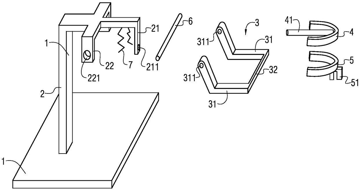
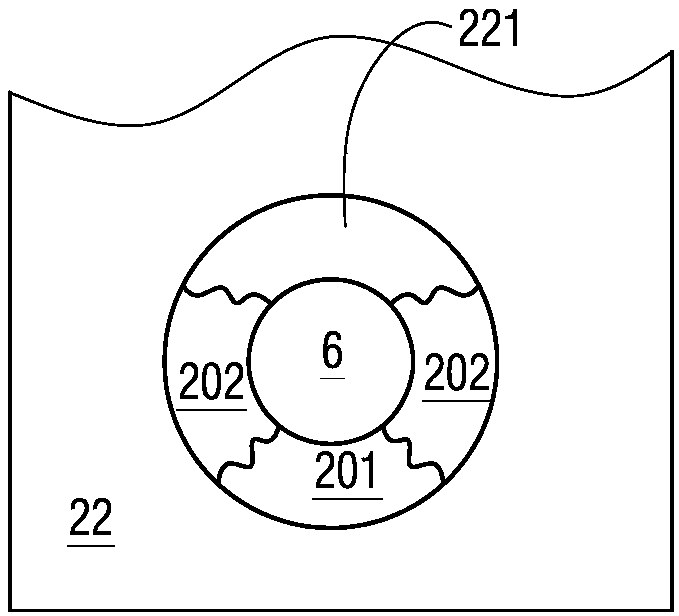
[0022] figure 2 It is a schematic diagram of the principle of a partially decomposed three-dimensional structure of a central relationship position demonstration device according to a specific embodiment of the present invention, image 3 for figure 2 Schematic diagram of the principle of the coaxial connection between the middle connecting rod and the mounting hole; Figure 4 for figure 2 Schematic diagram of the principle of the non-axial connection state between the connecting rod and the mounting hole. figure 2 It is mainly used to describe the principle, so only a three-dimensional schematic view of the partial structure in the exploded state is given. see ...


PUM


Abstract

A centric relation position demonstration device comprises a base plate, an upper rack, a lower jaw simulation rack, an upper dental cast, and a lower dental cast; the application method comprises thefollowing steps: A, preparing the upper dental cast and the lower dental cast according to teaching demands; B, fitting the upper dental cast with the lower dental cast; C, enabling the upper and lower dental casts to form centric bite, and observing motion relations in the centric bite; D, simulating different centric relation positions, and observing influences on biting relations by differentcentric relation positions. The centric relation position demonstration device application method can directly display teeth biting relation changes caused by changes of position relations between a condyle and an articular fossa, thus providing clear and direct feelings for dentistry students and oral cavity clinic doctors to understand and analyze the centric relation positions.

Description

technical field [0001] The invention relates to the field of teaching aids, in particular to a method for using a central relationship position demonstration device. Background technique [0002] figure 1 It is a schematic diagram of the bone structure of the human head, see figure 1 As shown, the median relationship is the positional relationship between the lower jaw 101 and the upper jaw 102, and is the positional relationship of the condyle 103 in the glenoid fossa. When the teeth of the upper and lower jaws cannot determine a stable relationship between the upper and lower jaws, the only stable connection position available between the upper and lower jaws is the positional relationship between the condyle 103 and the glenoid fossa. Therefore, the centric relationship can be used clinically to establish a centric occlusion. There are many definitions of the median relationship, and there are seven editions of definitions in "The Glossary of Prosthodontic Terms". The...

Claims


Application Information

Patent Timeline
Patent Type & Authority Applications(China)
IPC IPC(8): G09B23/28
CPCG09B23/283
Inventor 彭菊香冯萍
Owner 彭菊香
Why Eureka
Try Eureka