Supercharge Your Innovation With Domain-Expert AI Agents!

Condensate drain

A technology for discharging devices and condensate, which is applied in steam engine devices, steam traps, machines/engines, etc., and can solve the problems that mechanical traps are not suitable for operation and cannot provide condensate data.

Active Publication Date: 2021-08-10
SPIRAX SARGO LTD
View PDF6 Cites 0 Cited by
  • Summary
  • Abstract
  • Description
  • Claims
  • Application Information

AI Technical Summary

Problems solved by technology

However, such mechanical traps are not well suited to operate in different pressure ranges and do not provide data on the condensate being drained

Method used


Image

  • Condensate drain
  • Condensate drain
  • Condensate drain

Examples


Embodiment Construction

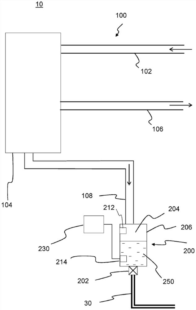
[0067] figure 1 A portion of an exemplary fluid flow network 10 including a fluid system 100 , a condensate drain 200 and a condensate return line 30 is shown. Fluid system 100 includes a fluid supply line 102 , a heat exchanger 104 , a fluid return line 106 , and a condensate drain line 108 . Fluid system 100 may be used to deliver any working fluid, such as refrigerant or water. In this example, the heat exchanger 104 defines a heat transfer chamber configured to receive a gaseous fluid from a fluid supply line 102 (the supply line 102 is located in an upper portion of the heat transfer chamber), And the gaseous fluid is discharged from the fluid return line 106 (the fluid return line 106 is located at the lower part of the heat transfer chamber).

[0068] A condensate drain line 108 is connected to the heat exchanger 104 at a lower portion of the heat exchanger to receive gaseous and / or liquid fluid from the heat exchanger 104 .

[0069] In one example, fluid system 100 ...


PUM


Abstract

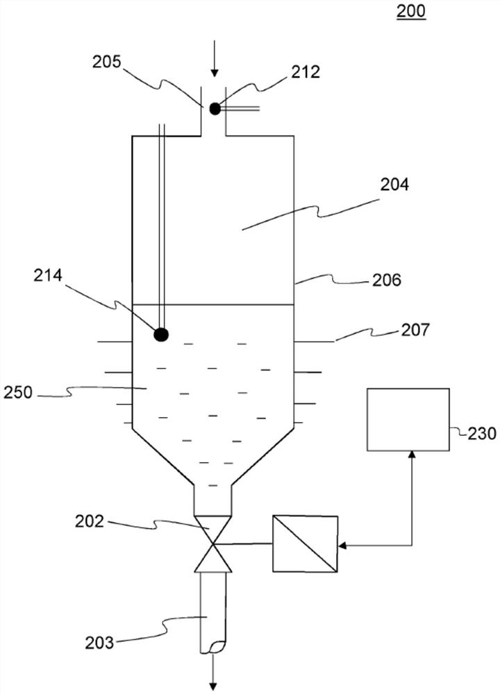
A condensate drain (200) comprising: a valve (202) for controlling discharge of condensate (250) from the condensate drain (200); a collection chamber (206) configured to receive the valve (202) Upstream of the multiphase fluid flow, comprising a gas phase and a condensed phase, a collection chamber (206) defines a collection volume (204) for collecting condensate (250) to be drained through the valve (202); sensor equipment for monitoring and valve Parameters related to the thermodynamic properties of the fluid upstream of (202); a controller (230), configured to monitor the collection of condensate based on the monitored parameters, and control the opening and closing of the valve (202) to regulate the valve (202) upstream collection of condensate; wherein the controller (230) is further configured to determine the amount of condensate to discharge from the collection volume (204) using a flow rate calculation for choked flow of vaporized liquid.

Description

technical field [0001] The invention relates to condensate drains. Background technique [0002] Condensate drains can be used to allow the condensed phase of a fluid to be drained while preventing the gaseous phase of the same fluid from being drained. A specific example of a condensate removal device in the environment of a steam system is a steam trap. [0003] It is known to provide a steam apparatus for generating useful energy in the form of steam and distributing it to a point of use in various industrial applications. [0004] The presence of excess condensate in the main steam plant is generally undesirable as it may act as a barrier to heat transfer and may also cause damaging "water hammer" and may even lead to corrosion of the pipes. Therefore, it is preferable to keep the steam in the steam equipment so that it is as dry as possible. To accomplish this, the condensate is usually removed from the lowest point of the main equipment piping through one or more di...

Claims


Application Information

Patent Timeline
Patent Type & Authority Patents(China)
IPC IPC(8): F16T1/48F16T1/02F01K25/08
CPCF01K25/08F16T1/02F16T1/48
Inventor J·米勒D·奥利弗P·亚瑟
Owner SPIRAX SARGO LTD
Features
  • R&D
  • Intellectual Property
  • Life Sciences
  • Materials
  • Tech Scout
  • Unparalleled Data Quality
  • Higher Quality Content
  • 60% Fewer Hallucinations
Learn More