

Velocity inversion method based on vertical and horizontal spatial constraints
A velocity inversion and space constraint technology, applied in seismic signal processing, etc., can solve problems such as difficulty in obtaining inversion results, and achieve the effect of easy operation, simple operation, and improved accuracy
Active Publication Date: 2018-12-28
CHINA PETROLEUM & CHEM CORP +1
View PDF10 Cites 4 Cited by
- Summary
- Abstract
- Description
- Claims
- Application Information
AI Technical Summary
Problems solved by technology
Because the commonly used velocity inversion method is difficult to obtain reasonable inversion results in data with sudden changes in velocity in areas with complex structures, the work of interpretation requires a velocity inversion method that can solve various complex structures
Method used
View moreImage
Smart ImageViewing Examples

Examples
Embodiment Construction
Login to View More PUM
 Abstract
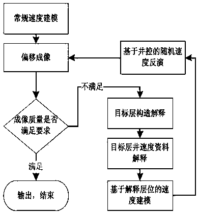
The invention provides a velocity inversion method based on vertical and horizontal spatial constraints. The velocity inversion method based on the vertical and horizontal spatial constraints comprises: S1, establishing an initial velocity model and carrying out migration imaging; S2, carrying out analysis on an imaging result, and carrying out depth domain error analysis by using existing well logging information; S3, establishing a basic structural control model of a target horizon; S4, on the basis of structural interpretation, carrying out velocity description by using well data corresponding to a target layer, and establishing a relatively accurate velocity model for the target layer; S5, establishing a velocity model by using the structural interpretation and well logging interpretation information; and S6, carrying out velocity inversion of the target horizon by using a well data controlled random velocity inversion method. The velocity inversion method based on the vertical andhorizontal spatial constraints adopts the velocity inversion method based on actual earthquake recorded amplitude information and a well velocity distribution probability, and well solves the velocity inversion problem in various complex areas.
Description
technical field The invention relates to the technical field of oil and gas exploration seismic data processing, in particular to a velocity inversion method based on vertical and horizontal space constraints. Background technique Velocity plays an important role in seismic data processing. There are many commonly used velocity inversion methods, such as velocity analysis, tomographic velocity inversion, logging velocity interpolation, and full waveform inversion. The commonly used velocity analysis method obtains the root mean square velocity, and the obtained velocity is based on the velocity analysis results obtained under the assumption of a horizontal layered medium. The tomographic velocity depends on the picked-up effective wave travel time, and the reliability of the inversion results is poor in the velocity mutation region. The method of well logging velocity interpolation depends heavily on the distribution of well logging, and the velocity results near the well l...
Claims
Login to View More Application Information
Patent Timeline
 Patent Type & AuthorityApplications(China)
IPC IPC(8): G01V1/28
CPCG01V1/28
Inventor李凌云张云银傅金荣陈震林孙治国董月昌王蓬
OwnerCHINA PETROLEUM & CHEM CORP