Image shake correction device, main body device, image shake correction method, and recording medium

A technology for calibrating devices and subjects, applied in measurement devices, image communication, instruments, etc., can solve problems such as discomfort, no photographer, etc., to achieve the effect of stable panning images

Active Publication Date: 2021-03-19
OM DIGITAL SOLUTIONS CORP
View PDF9 Cites 0 Cited by
  • Summary
  • Abstract
  • Description
  • Claims
  • Application Information

AI Technical Summary

Problems solved by technology

[0021] On the other hand, in the case of slow panning, no technical means have been proposed to solve the discomfort that may be caused to the photographer

Method used


Image

  • Image shake correction device, main body device, image shake correction method, and recording medium
  • Image shake correction device, main body device, image shake correction method, and recording medium
  • Image shake correction device, main body device, image shake correction method, and recording medium

Examples


no. 1 Embodiment approach

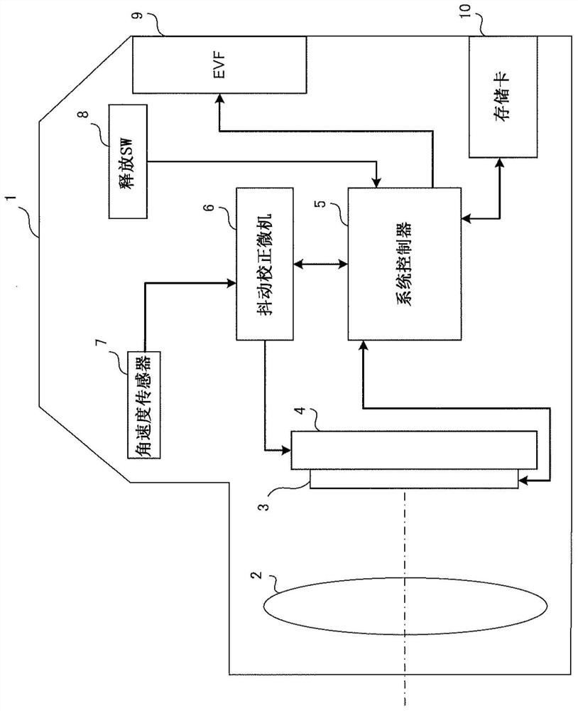
[0079] figure 1 It is a diagram showing a configuration example of a camera that is an imaging device having an image shake correction device according to the first embodiment of the present invention.

[0080] Such as figure 1 As shown, the camera 1 includes a photographing optical system 2, an imaging element 3, a drive unit 4, a system controller 5, a shake correction microcomputer 6, an angular velocity sensor 7, a release SW (switch: switch) 8, an EVF (electric viewfinder: electronic viewfinder) ) 9 and memory card 10.

[0081] The imaging optical system 2 includes a focus lens and a zoom lens, and forms an image of a light beam from a subject on the imaging element 3 .

[0082] The imaging element 3 converts the subject image (subject optical image) formed by the imaging optical system 2 into an electrical signal. The imaging element 3 is, for example, an image sensor such as a CCD (charge coupled device) or a CMOS (complementary metal oxide semiconductor).

[0083...

no. 2 Embodiment approach

[0134] Next, a second embodiment of the present invention will be described. In this description, only differences from the first embodiment will be described. In addition, the same reference numerals are assigned to the same constituent elements as those of the first embodiment, and description thereof will be omitted.

[0135] Figure 5 It is a diagram showing an example of the functional configuration of the pan detection unit 63 according to the second embodiment.

[0136] Such as Figure 5 As shown, the pan detection unit 63 of the second embodiment includes a first pan detection unit 631 , a second pan detection unit 632 , and a logic circuit 633 .

[0137] The first pan detection unit 631 detects the first pan and detects the direction of the pan based on the angular velocity as a result of the processing by the signal processing unit 61, and outputs a first pan detection result signal and a first pan direction detection signal. result signal. More specifically, as...

no. 3 Embodiment approach

[0165] Next, a third embodiment of the present invention will be described. In this description, only differences from the first embodiment will be described. In addition, the same reference numerals are assigned to the same constituent elements as those of the first embodiment, and description thereof will be omitted.

[0166] Figure 8 It is a diagram showing an example of the functional configuration of the shake correction microcomputer 6 according to the third embodiment.

[0167] Such as Figure 8 As shown, the shake correction microcomputer 6 of the third embodiment is figure 2 The shake correction microcomputer 6 of the first embodiment shown further includes an amplitude determination unit 68 .

[0168] The amplitude determination unit 68 determines the upper limit when the trimming process is performed by the limiting unit 64 when no panning is detected, based on the angular velocity as a result of processing by the signal processing unit 61 from the current tim...


PUM


Abstract

Image shake correction device, main body device, image shake correction method and recording medium. The image shake correction device has: an angular velocity detection unit that detects the angular velocity; a first pan detection unit that detects the first pan based on the angular velocity; an LPF processing unit that performs LPF processing on the angular velocity; a second pan detection unit that detects the first pan based on the angular velocity; As a result of the processing, a second pan with a pan speed slower than the first pan is detected; the HPF processing unit performs HPF processing on the angular velocity; the calculation unit uses the detection result of the first pan detection unit or the second pan detection unit and The processing result of the HPF processing part calculates the image shake correction amount; and the drive instruction part drives the image shake correction mechanism according to the image shake correction amount, and when the first shake detection part detects the first shake or the second shake When the shot detection unit detects the second pan, the characteristics of one or both of the HPF processing unit and the calculation unit are changed.

Description

technical field [0001] The present invention relates to an image shake correction device for correcting image shake, a main body device having the image shake correction device, an image shake correction method of the image shake correction device, and a recording medium. Background technique [0002] In recent digital cameras (hereinafter simply referred to as cameras), optical hand-shake correction is generally performed for viewfinder viewing (Finder View) during movie recording. Here, the viewfinder view means, for example, a subject image captured and displayed in real time (viewfinder display) during shooting standby, and is also referred to as a live view (Live View). [0003] When performing hand-shake correction on continuous images such as viewfinder framing when shooting movies, it prevents image disturbances caused by hand-shake and provides a good appearance. However, when there is a change in the posture of the camera due to the photographer's intention, camer...

Claims


Application Information

Patent Timeline
Patent Type & Authority Patents(China)
IPC IPC(8): H04N5/232
CPCH04N23/6812H04N23/687G01P3/00G03B2217/005G03B2205/0007G02B27/646
Inventor 土屋仁司
Owner OM DIGITAL SOLUTIONS CORP
Why Eureka
Try Eureka