Vehicle steering roll linkage mechanism and roll control method

A linkage mechanism and vehicle technology, applied to steering mechanisms, steering mechanisms of deflectable wheels, vehicle components, etc., can solve problems such as steering stability, poor ride comfort, failure to meet steering technical requirements, and inability to be directly applied

Active Publication Date: 2021-08-03
河南坐骑科技有限公司
View PDF8 Cites 0 Cited by
  • Summary
  • Abstract
  • Description
  • Claims
  • Application Information

AI Technical Summary

Problems solved by technology

[0002] The active roll control system improves the steering stability, smoothness, passing speed and safety of the vehicle when turning by controlling the vehicle's inclination to the inside of the turn; When the road surface is tilted, it automatically tilts at a certain angle to resist the centrifugal force and maintain a stable driving posture. The body roll is usually implemented in two ways: the independent roll of the body, and the linkage roll of the body and wheels. The steering movement of the vehicle is carried out independently without interfering with each other, and any steering mechanism can be used, but the handling stability and ride comfort of the vehicle are slightly worse when turning; the latter is the linkage roll method of the body and wheels, and the body roll and the vehicle steering movement affect each other , the handling stability, smoothness and safety of the vehicle are better when turning, but it needs to adopt two-wheel independent steering or four-wheel independent steering technology, adopt hydraulic drive, servo control steering wheels or servo motor drive, control steering wheels to meet the requirements of Ak However, the isosceles trapezoidal steering mechanism with simple structure and reliable operation does not meet the steering technical requirements under vehicle steering and roll conditions, and cannot be directly applied.

Method used


Image

  • Vehicle steering roll linkage mechanism and roll control method
  • Vehicle steering roll linkage mechanism and roll control method
  • Vehicle steering roll linkage mechanism and roll control method

Examples


Embodiment Construction

[0037] Embodiments of the present invention will be described below according to the accompanying drawings.

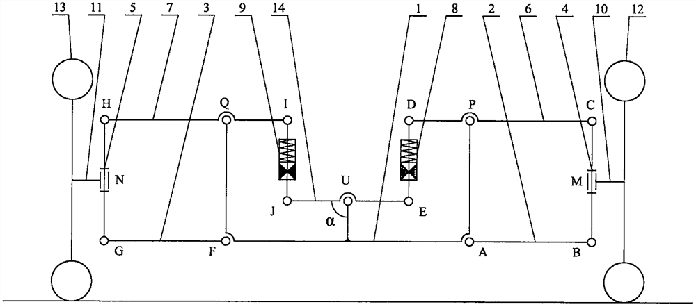
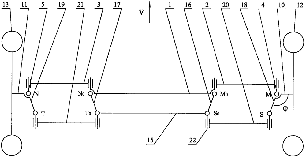
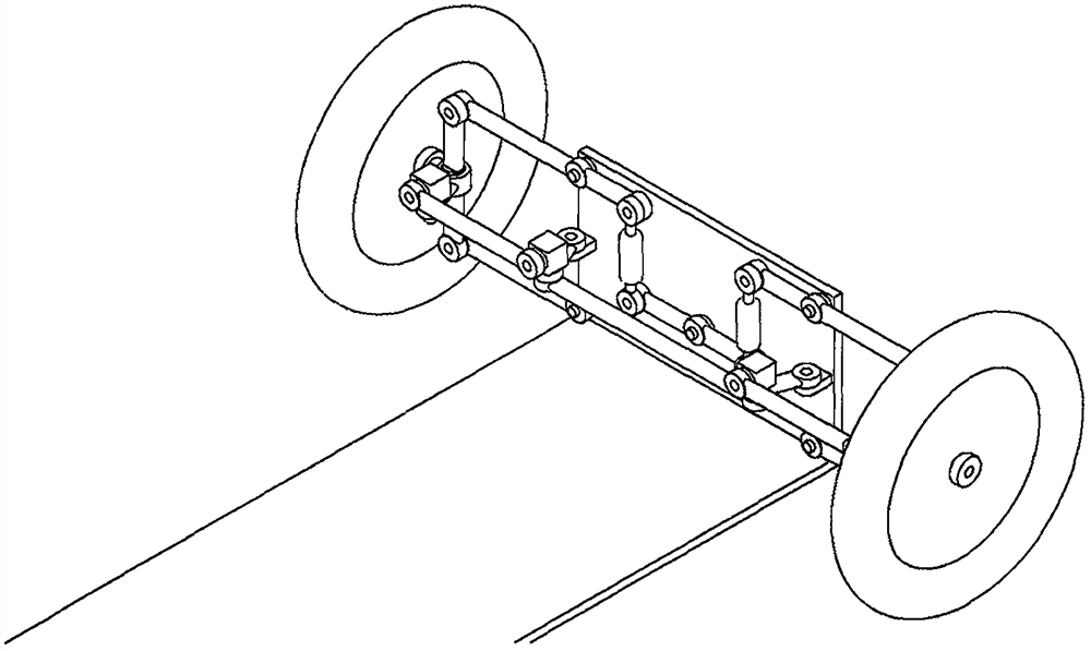
[0038] The vehicle steering roll linkage mechanism consists of a roll mechanism and a steering mechanism (such as image 3 shown);

[0039] figure 1 The schematic diagram of the roll mechanism is shown. The roll mechanism includes: the right suspension ABCDE is composed of the right lower link 2, the right steering knuckle main shaft 4, the right upper link 6 and the ends of the right shock absorber 8. Parallel to and perpendicular to the plane where the right suspension ABCDE is located, the right steering knuckle 10 is connected with the right steering knuckle main shaft 4 around its axis BC, and the right steering knuckle 10 is connected to the right wheel 12 and controls its direction; the left suspension FGHIJ is composed of the left pull rod 3, The left steering knuckle main shaft 5, the left upper link 7 and the left shock absorber 9 are sequentially connected...


PUM


Abstract

The invention relates to the technical field of vehicle chassis, and discloses a vehicle steering roll linkage mechanism and a roll control method. The vehicle steering roll linkage mechanism is composed of a roll mechanism and a steering mechanism. The left and right steering arms of the steering mechanism are respectively connected to the side The left and right steering knuckles of the tilting mechanism are fixed at a fixed angle. The two mechanisms share the main shaft of the vehicle body and the left and right steering knuckles. Two dynamic parallelograms with two degrees of freedom are linked to realize independent control of body roll and vehicle steering. It can realize three working conditions of steering roll, independent roll or independent steering, and the wheelbase of the vehicle remains unchanged; it is applied to the active roll of the vehicle body when the vehicle is turning, so that the vehicle automatically tilts at a certain angle when cornering or driving on an inclined road. Resists centrifugal force or rollover force to maintain a stable driving posture.

Description

technical field [0001] The invention relates to a vehicle steering roll linkage mechanism and a roll control method, belonging to the technical field of vehicle chassis, in particular to the technical category of vehicle steering under the condition of vehicle body roll. Background technique [0002] The active roll control system improves the steering stability, smoothness, passing speed and safety of the vehicle when turning by controlling the vehicle's inclination to the inside of the turn; When the road surface is tilted, it automatically tilts at a certain angle to resist the centrifugal force and maintain a stable driving posture. The body roll is usually implemented in two ways: the independent roll of the body, and the linkage roll of the body and wheels. The steering movement of the vehicle is carried out independently without interfering with each other, and any steering mechanism can be used, but the handling stability and ride comfort of the vehicle are slightly ...

Claims


Application Information

Patent Timeline
Patent Type & Authority Patents(China)
IPC IPC(8): B62D9/02
CPCB62D9/02
Inventor 王亚魏文军
Owner 河南坐骑科技有限公司
Why Eureka
Try Eureka