A trigger timing synchronization method, device, equipment and storage medium for a line scan camera

A linear array camera and timing synchronization technology, applied in TV, color TV parts, TV system parts, etc., can solve problems such as image distortion, image stretching or distortion, missed shooting of detected objects, etc., to achieve Solve image stretching or image distortion, improve the effect of image shooting

Active Publication Date: 2020-03-27
SHENZHEN SHENGSHI INTELLIGENT EQUIP
View PDF6 Cites 0 Cited by
  • Summary
  • Abstract
  • Description
  • Claims
  • Application Information

AI Technical Summary

Problems solved by technology

In this way, when scanning, if the frame trigger signal a of the line scan camera is not synchronized with the signal (Y-axis drive signal c) of the object to be photographed, the image captured by the camera will be stretched or distorted, for example, as figure 2 Among them, when the frame trigger signal a (high level at trigger position 2) is triggered earlier than the Y-axis drive signal c (the detected object starts to move at t=t1), since the detected object does not move, the The actual detected object is shot multiple times at the same position, and image stretching occurs; when the frame trigger signal a (high level at trigger position 3) is triggered later than the Y-axis drive signal c (the detected object is at t = start to move at t1), because the detected object has moved a certain distance, the actual detected object is partially missed, and image distortion occurs

Method used


Image

  • A trigger timing synchronization method, device, equipment and storage medium for a line scan camera
  • A trigger timing synchronization method, device, equipment and storage medium for a line scan camera
  • A trigger timing synchronization method, device, equipment and storage medium for a line scan camera

Examples


Embodiment 1

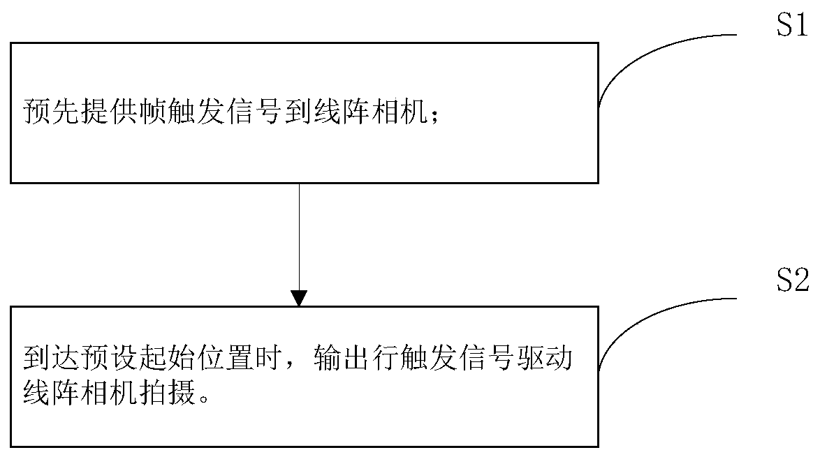
[0031] image 3 It is a schematic flow chart of a line array camera trigger timing synchronization method of the present invention, refer to image 3 , a line array camera trigger timing synchronization method, used in a line array camera scanning system, the line array camera scanning system includes an imaging component for photographing an object to be inspected, a carrier for placing an object to be inspected, and a Y-axis motor. The tool moves along the Y-axis driven by the Y-axis motor, the photographing component includes a line camera, and the method includes steps S1 to S2.

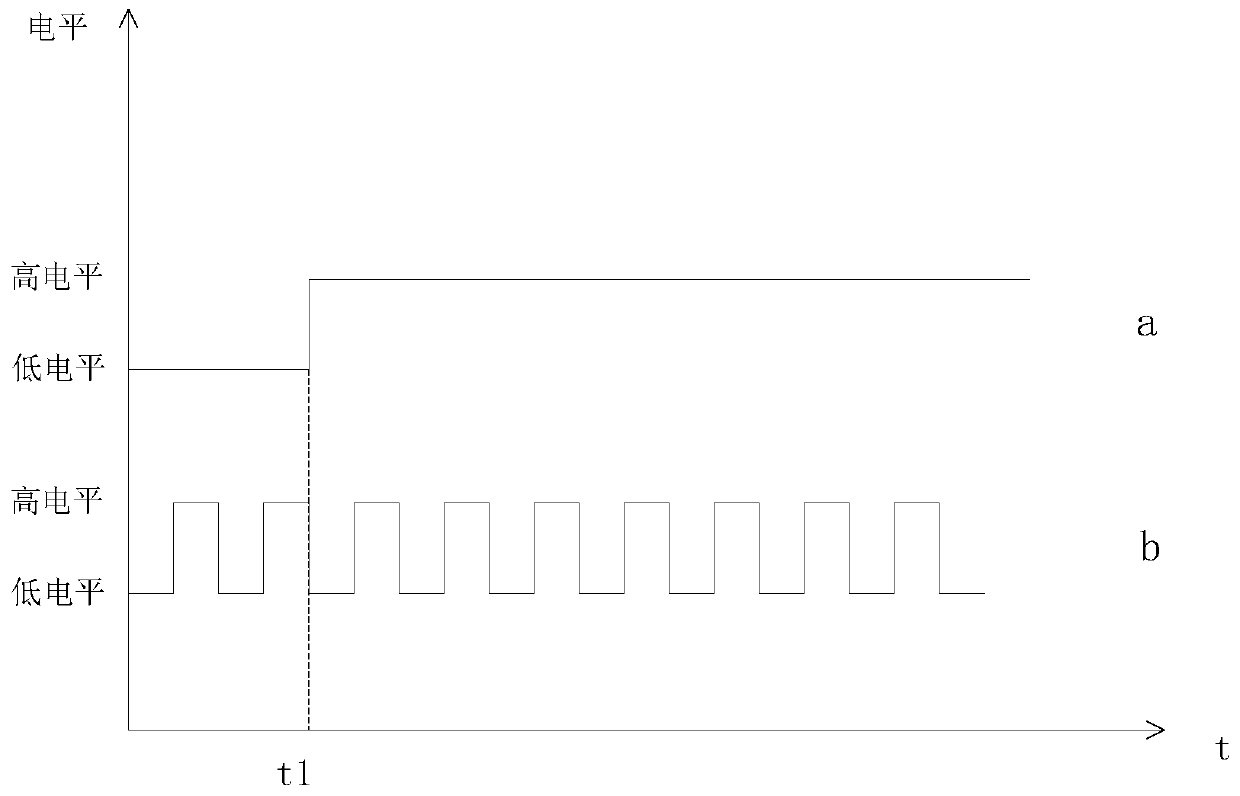
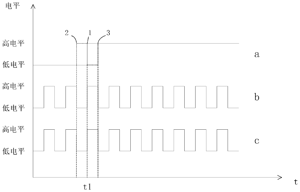
[0032] S1, providing frame trigger signal (high level) to the line scan camera in advance;

[0033] S2, when the preset start position is reached, the line trigger signal is output to drive the line scan camera to shoot.

[0034] Wherein, the starting position is set after the start of the frame trigger signal.

[0035] In this embodiment, the line scan camera scanning system further includes ...

Embodiment 2

[0039] Figure 4 It is a module block diagram of a line array camera trigger timing synchronization device of the present invention, refer to Figure 4 , a line-scan camera trigger timing synchronization device is used in a line-scan camera scanning system. The line-scan camera scanning system includes a shooting part for shooting an object to be detected, a carrier for placing the object to be detected, and a Y-axis motor. The tool moves along the Y-axis driven by the Y-axis motor, the photographing component includes a line camera, and the synchronization device also includes a first trigger module and a second trigger module.

[0040] The first trigger module is used to provide a frame trigger signal (high level) to the line scan camera in advance. In a specific embodiment, the first triggering module is set in the line-scan camera scanning system and connected to the line-scan camera, and the first triggering module is a controller.

[0041] The second trigger module is ...

Embodiment 3

[0047] The embodiment of the present invention also provides a line-scan camera trigger timing synchronization device, including:

[0048] at least one processor; and a memory communicatively coupled to the at least one processor; wherein,

[0049] The memory stores instructions that can be executed by at least one processor, and the instructions are executed by the at least one processor, so that the at least one processor can execute the above-mentioned method for synchronizing trigger timing of line scan cameras.


PUM


Abstract

The invention discloses a line scan camera triggering time-sequence synchronization method, which is used for a line scan camera scanning system. The line scan camera scanning system includes a photographing part used for photographing a to-be-detected object, a carrier used for placing the to-be-detected object and a Y-axis motor. The carrier moves along a Y-axis under driving of the Y-axis motor. The photographing part includes a line scan camera. The method includes the steps of: providing a frame triggering signal to the line scan camera in advance; and outputting a row triggering signal to drive photographing of the line scan camera when a preset start position is reached, wherein the start position is set after starting of the frame triggering signal. The invention also discloses a line scan camera triggering time-sequence synchronization device, line scan camera triggering time-sequence synchronization equipment and a storage medium, and relates to the technical field of cameras. The line scan camera triggering time-sequence synchronization method, the line scan camera triggering time-sequence synchronization device, the line scan camera triggering time-sequence synchronization equipment and the storage medium solve the problem of stretching or distortion of an image shot by a line scan camera in the prior art, and improve image shooting effect.

Description

technical field [0001] The present invention relates to the technical field of cameras, in particular to a trigger timing synchronization method, device, device and storage medium of a line scan camera. Background technique [0002] The line scan camera collects at high speed. After each line is collected, it just moves to the next unit precision length, and continues to collect the next line. In this way, a two-dimensional picture will be assembled after a period of time, which is similar to that collected by an area array camera. picture of. Such as figure 1 As shown, the shooting mechanism of the line scan camera is generally as follows: when the frame trigger signal a is at a high level, each line pulse trigger signal b shoots once. [0003] In the prior art, the object to be detected usually moves in the Y-axis direction following the vehicle, such as figure 2 As shown, the carrier is driven by the Y-axis drive signal c provided by the Y-axis linear motor driver, an...

Claims


Application Information

Patent Timeline
Patent Type & Authority Patents(China)
IPC IPC(8): H04N1/03H04N5/04
CPCH04N1/03H04N5/04
Inventor 薛凯谢镐泽李亚坤张晋陈永强
Owner SHENZHEN SHENGSHI INTELLIGENT EQUIP
Why Eureka
Try Eureka