


Quick Research
Generate reliable direction feasibility study reports for your R&D in just a few steps.

Technical Q&A
Discover and master advanced knowledge NOW. Basics, ideas, possibilities, all at once.

Find Solutions
As an expert in R&D theories, this can generate solutions to your technical problems instantly.

Evaluate Feasibility
Analyze your overall solution with one click, know your potential R&D risks in advance.

Monitor Landscape
Get weekly tech updates, stay abreast of the latest tech innovations and key insights.
Continuous pyrolysis apparatus and continuous pyrolysis method for coal direct liquefaction residue
A technology of direct liquefaction and pyrolysis of coal, which is applied in special forms of dry distillation, petroleum industry, coking ovens, etc. It can solve the problems of coking oven leaks that easily cause major accidents, difficulty in crushing semi-coke, and high sealing requirements. To achieve the effect of continuous pyrolysis
- Summary
- Abstract
- Description
- Claims
- Application Information
AI Technical Summary
Problems solved by technology
Method used
Image

Examples
Embodiment 1
[0048] This embodiment is used to illustrate the continuous pyrolysis device and its method suitable for direct coal liquefaction residue of the present invention.
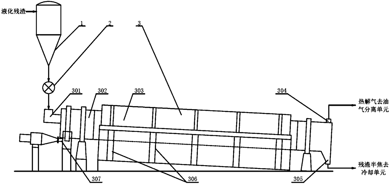
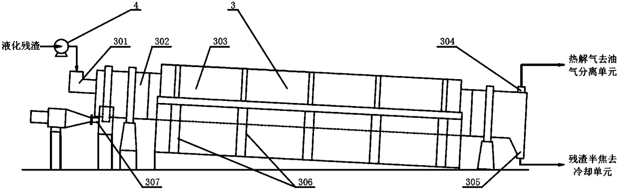
[0049] use figure 2 In the continuous pyrolysis device shown, the coal direct liquefaction residue (temperature is 310°C) is pumped to the feed port 301 through the feed pump 4 at a flow rate of 1000kg / h and then enters the rotary drum roaster. Next, and under the rotation of the furnace drum of the rotary cylindrical roaster and the free movement of the metal rods inside, the coal direct liquefaction residue is continuously pyrolyzed (furnace body speed 0.9r / min, residence time 60min), to obtain Pyrolysis gas and hot semi-coke, the pyrolysis gas is discharged through the pyrolysis gas outlet 304 and enters the oil-gas separation unit for separation to obtain tar and flue gas, and the hot semi-coke enters the cooling unit from the semi-coke outlet for cooling to obtain semi-coke products.
[0050] After 10 hours...
Embodiment 2
[0052] This embodiment is used to illustrate the continuous pyrolysis device and its method suitable for direct coal liquefaction residue of the present invention.
[0053] According to the method described in embodiment 1, the difference is that the rotating speed of the rotary drum roaster is 1.4r / min, the residence time is 39min, and others are all the same as in embodiment 1.
[0054] After 10 hours of continuous operation, the total direct coal liquefaction residue is 10,000kg, the resulting semi-coke product output is 8,124kg, the total output of tar and water is 1,064kg, and the flue gas output is 812kg. Among them, the particle size of the semi-coke obtained in this process is between 0- 30mm.
PUM
| Property | Measurement | Unit |
|---|---|---|
| diameter | aaaaa | aaaaa |
| particle size | aaaaa | aaaaa |
| particle size | aaaaa | aaaaa |
Abstract
Description
Claims
Application Information
 - R&D Engineer
- R&D Manager
- IP Professional
- Industry Leading Data Capabilities
- Powerful AI technology
- Patent DNA Extraction
Browse by: Latest US Patents, China's latest patents, Technical Efficacy Thesaurus, Application Domain, Technology Topic, Popular Technical Reports.
© 2024 PatSnap. All rights reserved.Legal|Privacy policy|Modern Slavery Act Transparency Statement|Sitemap|About US| Contact US: help@patsnap.com