
Continuous pyrolysis device and method suitable for direct coal liquefaction residue

A technology of direct liquefaction and pyrolysis of coal, which is applied in special carbonization, coking ovens, petroleum industry, etc. It can solve the problems of major accidents caused by air leakage in coking ovens, high sealing requirements, and high operating costs, so as to facilitate continuous The effect of pyrolysis

Active Publication Date: 2021-04-06
CHNA ENERGY INVESTMENT CORP LTD +1
View PDF5 Cites 0 Cited by
  • Summary
  • Abstract
  • Description
  • Claims
  • Application Information

AI Technical Summary

Problems solved by technology

However, due to the strong adhesion of liquefied residues in the molten state, it is still difficult for the differential speed twin-screw conveying device to achieve the purpose of pulverizing semi-coke, and the negative pressure operation costs are high, and the requirements for sealing are too high , coking furnace air leakage is likely to cause major accidents

Method used


Image

  • Continuous pyrolysis device and method suitable for direct coal liquefaction residue
  • Continuous pyrolysis device and method suitable for direct coal liquefaction residue
  • Continuous pyrolysis device and method suitable for direct coal liquefaction residue

Examples


Embodiment 1

[0048] This embodiment is used to illustrate the continuous pyrolysis device and its method suitable for direct coal liquefaction residue of the present invention.

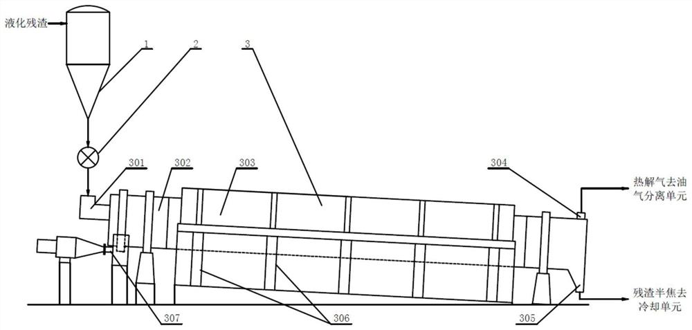
[0049] use figure 2 In the continuous pyrolysis device shown, the coal direct liquefaction residue (temperature is 310°C) is pumped to the feed port 301 through the feed pump 4 at a flow rate of 1000kg / h and then enters the rotary drum roaster. Next, and under the rotation of the furnace drum of the rotary cylindrical roaster and the free movement of the metal rods inside, the coal direct liquefaction residue is continuously pyrolyzed (furnace body speed 0.9r / min, residence time 60min), to obtain Pyrolysis gas and hot semi-coke, the pyrolysis gas is discharged through the pyrolysis gas outlet 304 and enters the oil-gas separation unit for separation to obtain tar and flue gas, and the hot semi-coke enters the cooling unit from the semi-coke outlet for cooling to obtain semi-coke products.

[0050] After 10 hours...

Embodiment 2

[0052] This embodiment is used to illustrate the continuous pyrolysis device and its method suitable for direct coal liquefaction residue of the present invention.

[0053] According to the method described in embodiment 1, the difference is that the rotating speed of the rotary drum roaster is 1.4r / min, the residence time is 39min, and others are all the same as in embodiment 1.

[0054] After 10 hours of continuous operation, the total direct coal liquefaction residue is 10,000kg, the resulting semi-coke product output is 8,124kg, the total output of tar and water is 1,064kg, and the flue gas output is 812kg. Among them, the particle size of the semi-coke obtained in this process is between 0- 30mm.


PUM

PropertyMeasurementUnit
diameteraaaaaaaaaa
diameteraaaaaaaaaa
particle sizeaaaaaaaaaa

Abstract

The invention relates to the field of continuous pyrolysis of coal direct liquefaction residue, in particular to a continuous pyrolysis device and method suitable for coal direct liquefaction residue. The device includes: a feeding unit, a pyrolysis unit and a discharge unit, the pyrolysis unit includes a rotary pyrolysis reactor (3) suitable for pyrolysis of coal direct liquefaction residue, the rotary pyrolysis reactor (3) A freely movable metal rod is arranged in the reaction chamber (302). The continuous pyrolysis device of the present invention skillfully arranges freely movable metal rods in the reaction chamber, so that the semi-coke produced by the pyrolysis of coal direct liquefaction residues can be pulverized online under the impact of freely moving metal rods, which is beneficial to coal directly Continuous pyrolysis of liquefaction residues.

Description

technical field [0001] The invention relates to the field of continuous pyrolysis of coal direct liquefaction residue, in particular to a continuous pyrolysis device and method suitable for coal direct liquefaction residue. Background technique [0002] In the existing direct coal liquefaction process, the conversion rate of coal cannot reach 100%, and there will always be unreacted coal, inorganic minerals and some catalysts in the solid form. They are mixed with liquefied oil, and various liquefaction processes use different solid-liquid separation methods to separate them from liquefied oil. The unseparated liquefied oil and the remaining solid matter are collectively called liquefaction residue, which is one of the by-products of the liquefaction process. The output of liquefaction residue accounts for about 30% of the feed coal. Take the Shenhua Coal Direct Liquefaction Demonstration Project as an example. Its scale produces 5Mt of oil products per year. The first pro...

Claims


Application Information

Patent Timeline
Patent Type & Authority Patents(China)
IPC IPC(8): C10B53/00C10B57/00
CPCC10B53/00C10B57/00
Inventor 陈强索娅孙永伟朱豫飞
Owner CHNA ENERGY INVESTMENT CORP LTD
Learn More