

Underflow energy dissipation structure for allowing flaring piers to extend to stilling basin
A technology of bottom flow energy dissipation and wide tail pier, which is applied in marine engineering, construction, barrage/weir, etc., can solve the problems of increased water drop out of the pool, pool depth and pool growth, and large single-width flow before jumping. Achieve the effect of reducing energy dissipation pressure, reducing design size and saving engineering costs
Pending Publication Date: 2019-03-19
云南省水利水电勘测设计院
View PDF0 Cites 2 Cited by
- Summary
- Abstract
- Description
- Claims
- Application Information
AI Technical Summary
Problems solved by technology
However, when the pier extends downstream for a longer length, the water flow will not fully diffuse after entering the stilling pool, the water flow will be relatively concentrated, and the single-width flow before the jump will be larger
In order to meet the energy dissipation requirements, the length and depth of the stilling basin need to be increased accordingly, which will inevitably increase the investment of the project, and for the stilling basin equip
Method used
View moreImage
Smart ImageViewing Examples

Examples
 PUM
| Property | Measurement | Unit |
|---|---|---|
| Width | aaaaa | aaaaa |
Abstract
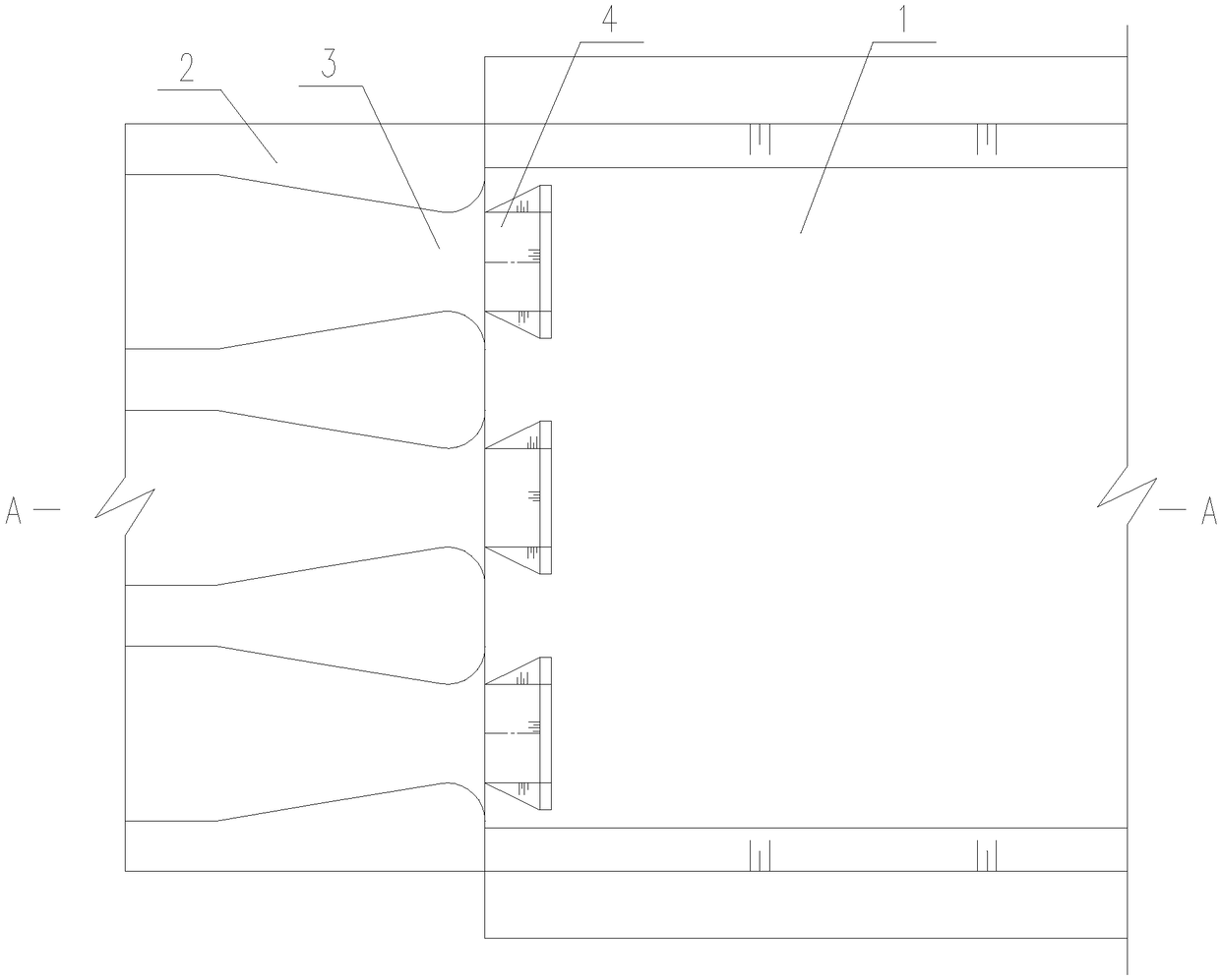
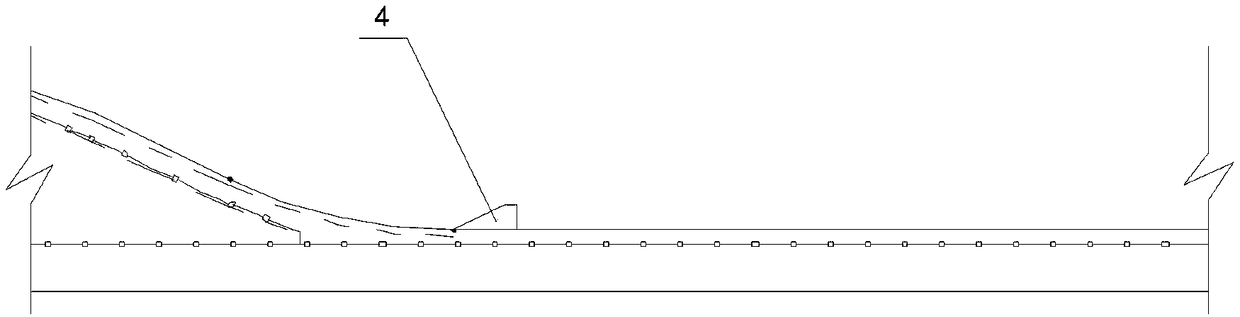
The invention provides an underflow energy dissipation structure for allowing flaring piers to extend to a stilling basin. The underflow energy dissipation structure comprises the stilling basin, themultiple flaring piers, multiple gate holes and flow diverting piers; the stilling basin is arranged on the downstream side of a gate pier; the multiple flaring piers and the multiple gate holes are arranged at the outlet end of the gate pier at intervals; the flow diverting piers are located in the stilling basin and directly face outlets of the gate holes, and the quantity of the flow divertingpiers is consistent with that of the gate holes; the upstream edges of the flow diverting piers and the tail ends of the flaring piers are located on the same horizontal line; the upstream starting width of the flow diverting piers is equal to the width of the outlets of the gate holes directly facing the flow diverting piersl; and the height of the flow diverting piers is 1/5-1/3 of the water depth of the outlets of the gate holes. According to the scheme, the flow diverting piers are arranged at the outlets of the gate holes, water flow drained through the gate holes is quickly and transversely diffused under the micro stirring and flow guiding effects of the flow diverting piers, water flow streams collide with one another to achieve energy dissipation, the energy dissipation pressure of the stilling basin is effectively reduced, therefore, the design size of the stilling basin can be decreased, and the engineering cost is reduced.
Description
technical field [0001] The invention relates to the technical field of hydraulic structure design, in particular to an underflow energy dissipation structure suitable for wide tail piers extending to stilling basins. Background technique [0002] When the overflow dam discharges floods, the water flowing down through the overflow orifice cannot quickly spread laterally after flowing out of the sluice hole due to the inertial effect. However, when the pier extends downstream for a long length, the water flow will not fully diffuse after entering the stilling pool, and the water flow will be relatively concentrated, and the single-width flow before the jump will be relatively large. In order to meet the energy dissipation requirements, the length and depth of the stilling basin need to be increased accordingly, which will inevitably increase the investment of the project, and for the stilling basin equipped with a tail sill, due to the increase in the height of the tail sill, ...
Claims
Login to View More Application Information
Patent Timeline
 IPC IPC(8): E02B8/06
CPCE02B8/06
Inventor 段鸿锋赵绍熙张玉蓉杨树德蒋汝成李磊
Owner 云南省水利水电勘测设计院