
Multi-evaporator loop heat pipe

A loop heat pipe and evaporator technology, applied in indirect heat exchangers, lighting and heating equipment, etc., can solve the problems affecting the integrated layout of the load system, not satisfying the coupling of complex heat sources, and the single shape of the evaporator, so as to improve the symmetrical design , Improve integration and expand application flexibility

Active Publication Date: 2019-04-05
SHANGHAI INST OF TECHNICAL PHYSICS - CHINESE ACAD OF SCI
View PDF7 Cites 3 Cited by
  • Summary
  • Abstract
  • Description
  • Claims
  • Application Information

AI Technical Summary

Problems solved by technology

Due to the limitation of bending, this method greatly affects the integrated layout of the load system. At the same time, the shape of the evaporator is relatively simple, which does not meet the requirements of complex heat source coupling.

Method used


Image

  • Multi-evaporator loop heat pipe
  • Multi-evaporator loop heat pipe
  • Multi-evaporator loop heat pipe

Examples


Embodiment Construction

[0022] In conjunction with the accompanying drawings, the specific implementation manners of the present invention will be described in detail below.

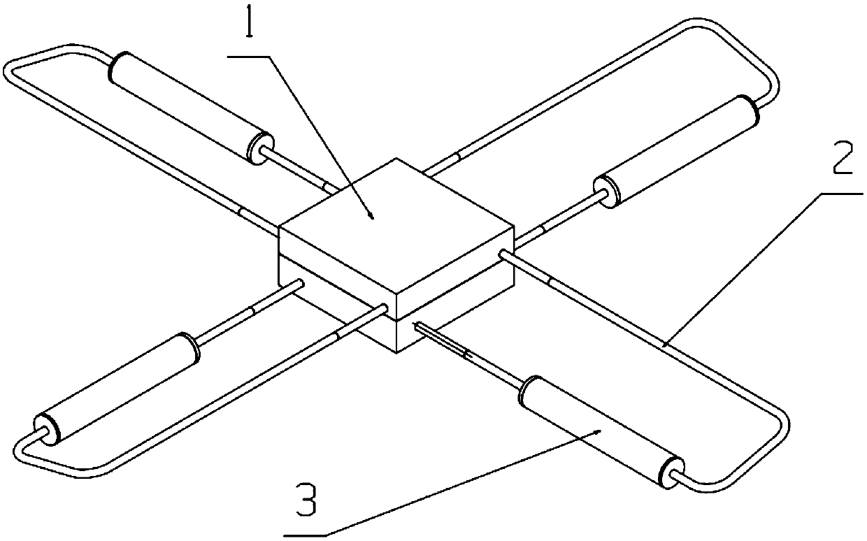
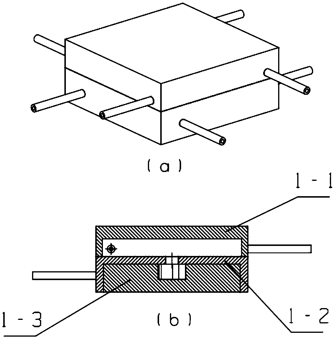
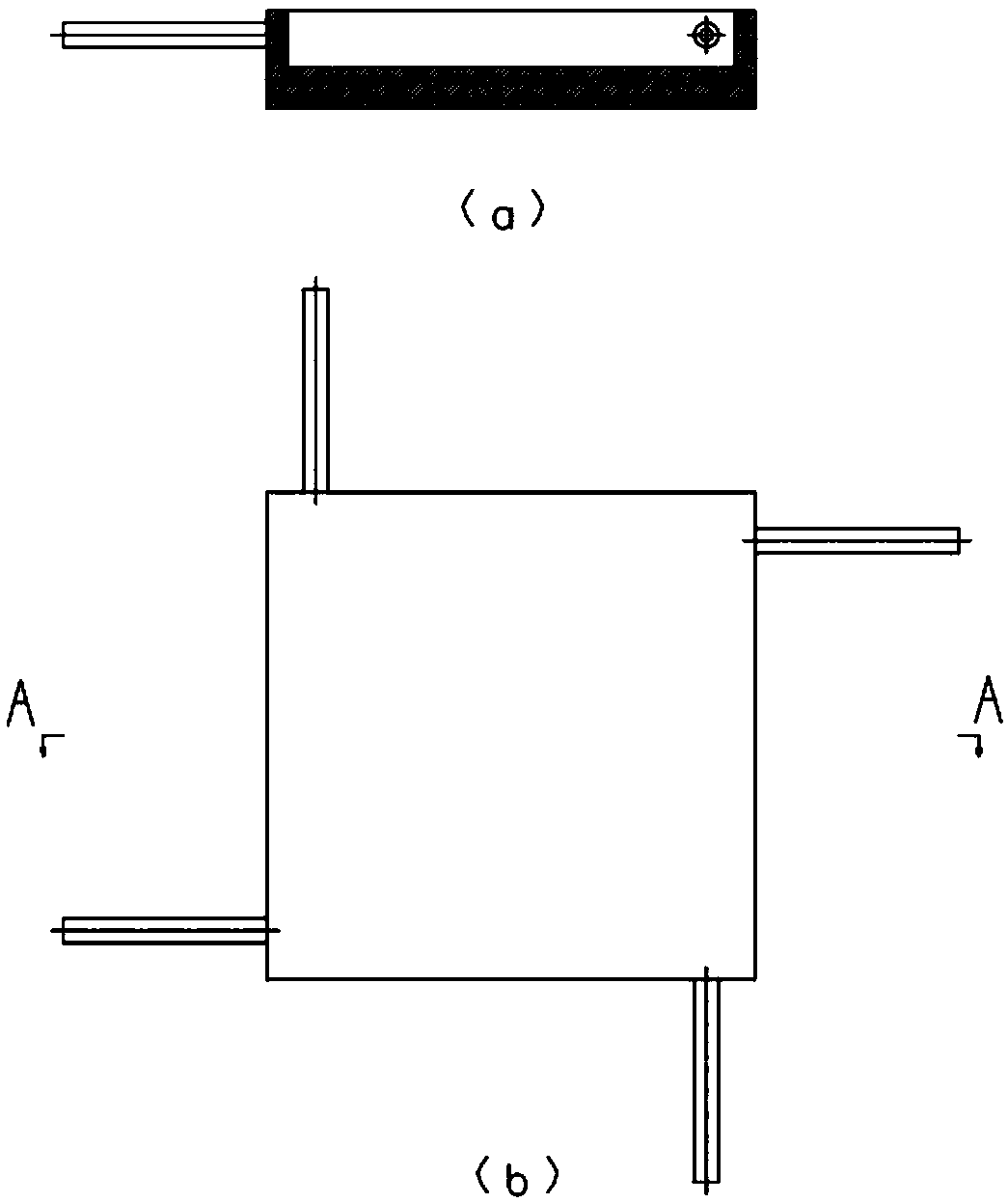
[0023] The structure of the novel multi-evaporator circuit heat pipe machine described in the present invention is as attached figure 1 As shown, it consists of three parts: a condenser (including a steam chamber 1-1, a confluence hole cover plate 1-2, and a condensation distribution plate 1-3), a gas-liquid pipeline 2, and an evaporator compensator unit 3. Among them, the condenser has a special layered design, which is composed of three components: the steam chamber 1-1, the confluence hole cover plate 1-2, and the condensation distribution plate 1-3. The evaporators 3 are located in four different directions of the condenser, and are distributed in a rotationally symmetrical manner around the periphery. The pipeline distribution method and working medium coupling method of the invention can be applied to multi-evaporator cir...


PUM


Abstract

The invention discloses a multi-evaporator loop heat pipe. The structure comprises a condenser, gas-liquid pipelines and four evaporator compensator units, the design method that four evaporators share one condenser is adopted, and the evaporators are gas-coupled. The condenser comprises a steam cavity, a converging hole cover plate and a condensing distributing plate; by the aid of the structurallayered design of the condenser, the evaporators are symmetrically distributed in the circumferential direction of the condenser, the design of pipelines are matched with the condenser, superheated steam is coupled in the steam cavity at the upper layer of the condenser, enters the lower-layer condensing distributing plate via converging holes for condensing heat exchange and flows out evenly along dispersing flow channels. Evaporator compensators adopt the integrated design of cylindrical structures. By the aid of the loop heat pipe, the design of an efficient heat transfer component under the condition that the single cold source faces multiple dispersed heat source is realized, and the heat uniformity among the evaporators is improved with the design method of gas coupling and uniformdistribution.

Description

technical field [0001] The invention relates to the field of phase change heat, in particular to a heat exchange element design based on the heat exchange principle of a loop heat pipe. Background technique [0002] With the development of space detection technology, the requirements for integration and light weight of satellite systems continue to increase, especially for applications such as large-scale infrared remote sensing detectors and wide-field ray telescopes, and the degree of integration of components on board satellites continues to increase. As the temperature rises, the power of the load is also continuously increased. In order to meet the higher detection requirements, the cooling demand of the large-area array is gradually increased, which puts forward higher requirements for the thermal control and thermal design of the load on the star. Therefore, it is necessary to simultaneously solve the problems of multi-heat source control, high heat flux dissipation, ...

Claims


Application Information

Patent Timeline
Patent Type & Authority Applications(China)
IPC IPC(8): F28D15/02F28D15/04
CPCF28D15/0266F28D15/04
Inventor 吴亦农鲁得浦谢荣建
Owner SHANGHAI INST OF TECHNICAL PHYSICS - CHINESE ACAD OF SCI
Learn More