An optical fiber pipe monitoring system

A monitoring system, optical fiber delay line technology, applied in transmission systems, electromagnetic wave transmission systems, electrical components, etc., can solve problems such as unavoidable losses, low technical content, and low efficiency

Active Publication Date: 2008-08-13
东莞先进光纤应用技术研究院有限公司
View PDF0 Cites 36 Cited by
  • Summary
  • Abstract
  • Description
  • Claims
  • Application Information

AI Technical Summary

Problems solved by technology

These methods are low in technical content, and generally have defects such as low efficiency, poor real-time performance, long response time, and poor anti-interference ability. Usually, the alarm can only be called after the monitoring facilities are damaged, and the practicability is restricted by both natural and human factors.
This "remedial" post-event detection technology can only reduce but not avoid losses

Method used


Image

  • An optical fiber pipe monitoring system
  • An optical fiber pipe monitoring system
  • An optical fiber pipe monitoring system

Examples


Embodiment

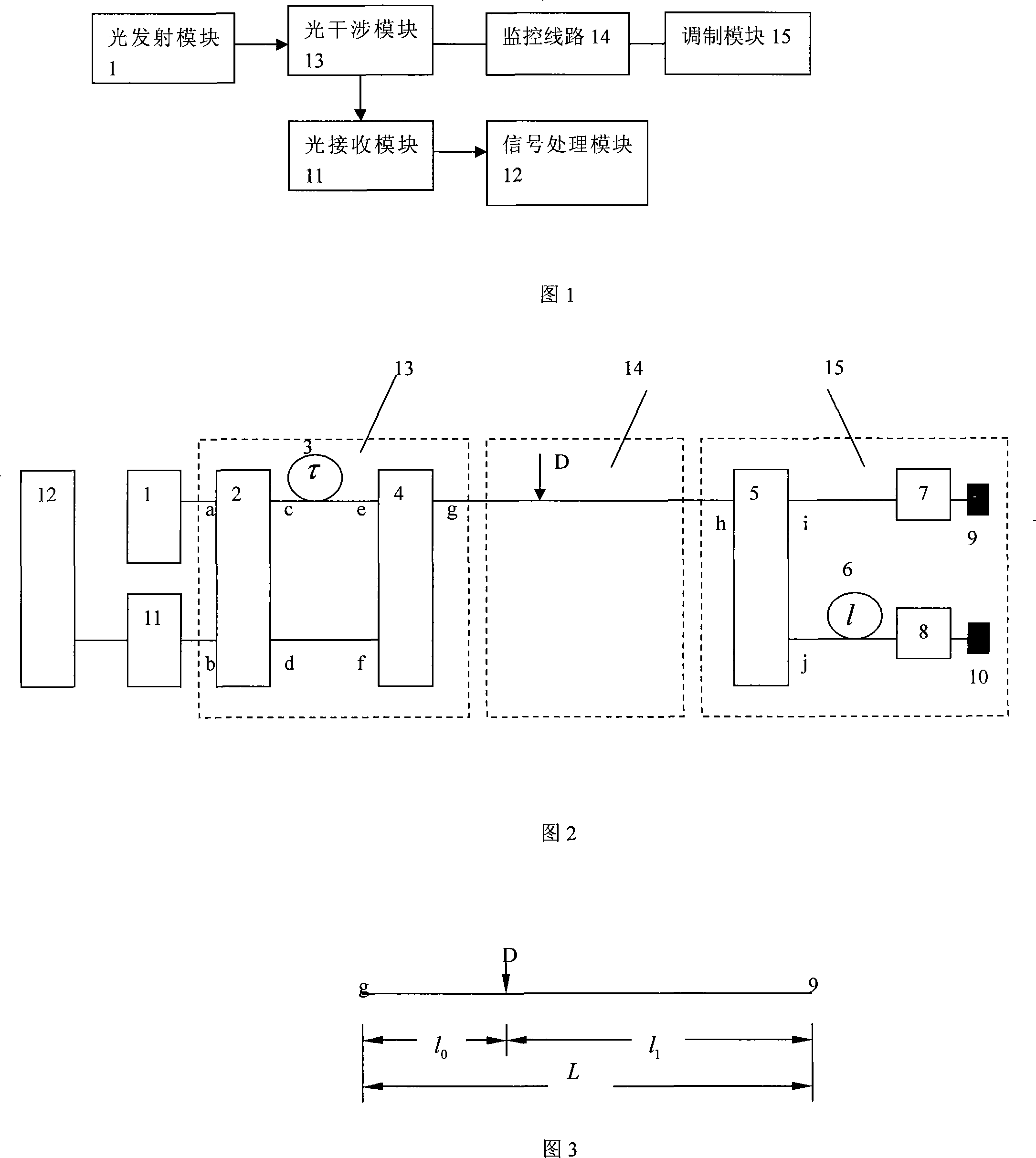
[0050] In this embodiment, the laser used is a SO3-B superluminescent diode (SLD) stable light source produced by the 44 Research Institute of the Electronics Group Corporation. The fiber optic coupler is a single-mode fiber optic coupler produced by Wuhan Institute of Posts and Telecommunications. The photodetector is an InGaAs photodetector produced by 44 Model GT322C500. The optical fiber used is a G652 single-mode optical fiber produced by Corning in the United States. The jumper is FC / PC single-mode fiber jumper produced by Wuhan Institute of Posts and Telecommunications, and the phase modulator is piezoelectric ceramics.

[0051] The connection of each component of the system is shown in Figure 2. The optical transmission module is connected to the a end of the first fiber coupler 2 with a FC / PC jumper cable, and the c end of the first fiber coupler 2 is connected to one end of the first fiber delay line 3. Fusion splicing, the other end of the first fiber delay line 3...


PUM


Abstract

The invention pertains to the pipeline monitoring technology, particularly a fiber pipeline monitoring system. The system is composed of an optical transmitter module, an optical interferometer module, a monitoring line, a modulator module, an optical receiver module and a signal processing module. The system can get two signals corresponding to different optical path positions of the same vibration though multiplexing a fiber interference system, compare the spectrum characteristics of the two signals, and eliminate the interference of the position information caused by the vibration information so as to obtain the accurate vibration position information under the condition that the system adds no photoelectric detector. The position information is obtained through the medium value of the spectrum amplitude ratio of the two signals, and the difference caused by the instability of the detection signal is eliminated, thus the accuracy of the location is greatly improved. The location function is realized with single-core fiber under the condition of not constituting a loop, thus the location monitoring can be realized by paving equal-distance main line along the petroleum pipe line, which has strong environmental applicability.

Description

technical field [0001] The invention belongs to the technical field of pipeline safety monitoring, in particular to an optical fiber pipeline monitoring system. Background technique [0002] Maintaining the security of infrastructure is a basic requirement for social stability and rapid economic development. At present, my country's monitoring of infrastructure such as oil and gas pipelines, power grids, and communication networks is mainly based on some production parameters of the facilities themselves (such as sudden pressure drops, abnormal changes in the liquid level of oil tanks in intermediate stations), manual inspections, and reports from passers-by, etc. means. These methods are low in technical content, and generally have defects such as low efficiency, poor real-time performance, long response time, and poor anti-interference ability. Often, the alarm can only be called after the monitoring facilities are damaged, and the practicability is restricted by both natu...

Claims


Application Information

Patent Timeline
Patent Type & Authority Applications(China)
IPC IPC(8): H04B10/08H04B10/12H04B10/077
Inventor 吴红艳唐璜肖倩贾波
Owner 东莞先进光纤应用技术研究院有限公司
Why Eureka
Try Eureka