Liquid crystal display device

a liquid crystal display and display device technology, applied in the field of liquid crystal display devices, can solve the problems of low display image quality with respect to the moving picture, long response time of the liquid crystal with respect to the signal, and relatively long time required until the liquid crystal attains a completely white state, etc., to achieve favorable display quality of the moving picture and eliminate the ghost

Inactive Publication Date: 2005-04-14
MITSUBISHI ELECTRIC CORP +1
View PDF12 Cites 39 Cited by
  • Summary
  • Abstract
  • Description
  • Claims
  • Application Information

AI Technical Summary

Benefits of technology

[0012] Therefore, the present invention provides a liquid crystal display device which can eliminate the “ghost” even when using the TN-type liquid crystal h

Problems solved by technology

However, since the LCD does not have a sufficient image quality in displaying a moving picture as compared with the CRT, improvement in the quality of the moving picture is expected.
One problem in such moving picture display results from a long response time of the liquid crystal with respect to the signal.
Consequently, as shown in FIG. 21, even when a voltage for a white display is applied to a liquid crystal which is providing a black display, a relatively long time is required until the liquid crystal attains a completely white state.
Furthermore, it is considered that the fact that displaying in the LCD is of a hold type, in which light emission of same amount continues unt

Method used


Image

  • Liquid crystal display device
  • Liquid crystal display device
  • Liquid crystal display device

Examples


embodiment 1

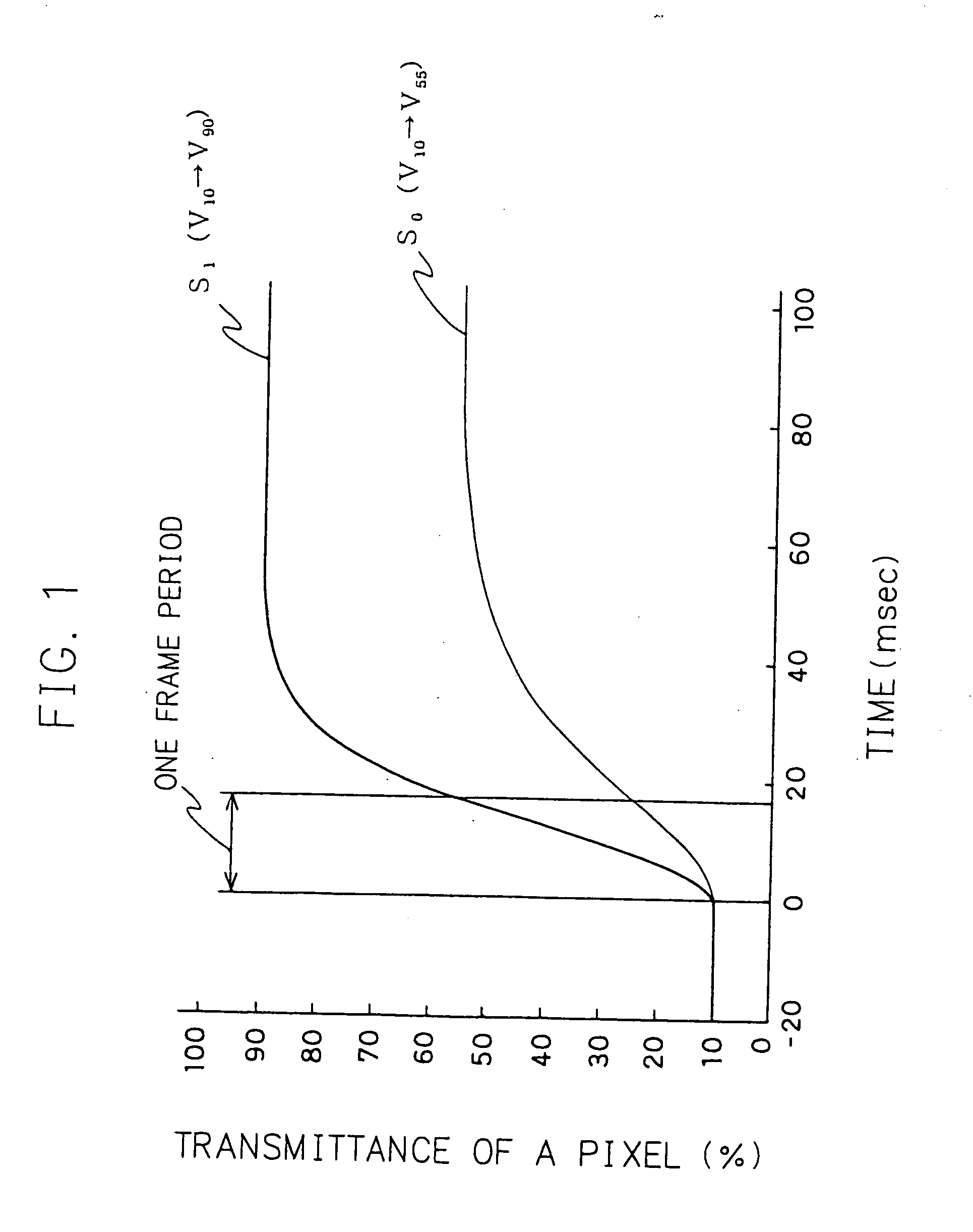
[0152] As has been already described, in the case where for example, a desired light transmittance is 55% in the conventional liquid crystal display device, namely in the case where the an image signal is input which designates a display having a light transmittance of 55%, a voltage V55 is applied to the liquid crystal, the voltage providing a light transmittance of 55% in the state in which a definite time passes away, and a response of the liquid crystal is almost completed. As a consequence, as shown by a thin line S0 in FIG. 1, the transmittance of the liquid crystal does not reach 55% in one frame which causes deterioration in the image quality of the moving picture display.

[0153] Therefore, according to the present embodiment, a voltage at which the liquid crystal comes to have a desired transmittance after one frame period is applied to the liquid crystal in the current frame. For example, as shown with a solid line S1 in FIG. 1, in the case where the desired transmittance ...

embodiment 2

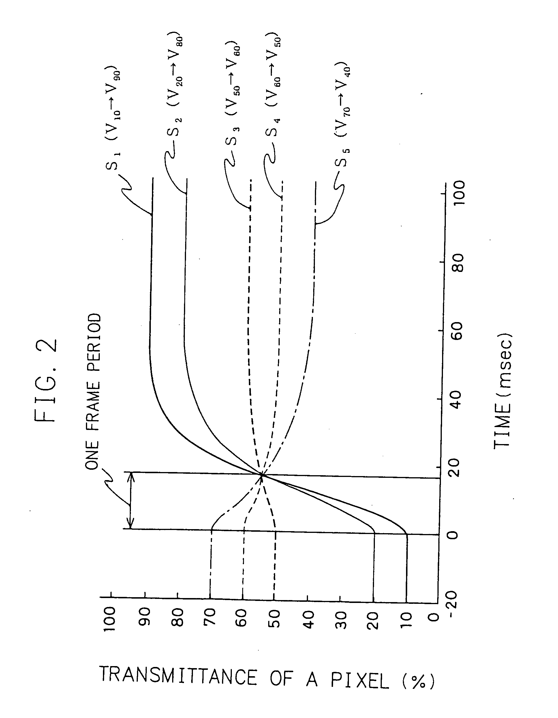
[0155]FIG. 2 is a view showing an applied voltage and a change in a transmittance of a liquid crystal in a current frame.

[0156] It can be seen that a display having a transmittance of 55% can be obtained by applying a voltage V80 at which the transmittance becomes 80% in the state of an approximate completion of the response of the liquid crystal in the current frame in the case where the transmittance of the former frame is 20% as shown with a thin line S2 of FIG. 2. In a similar manner, as apparent from the curved lines S1, S3, S4 and S5, in the case where it can be seen that a desired transmittance of 55% can be obtained after one frame period by applying voltages V90, V60, V50 and V40 respectively in the case where the transmittances of the former frame is 10%, 50%, 60% and 70% respectively.

[0157] In this manner, the voltage at which a desired transmittance is provided after one frame period can be defined uniformly from the transmittance of the former frame. Consequently, the...

embodiment 3

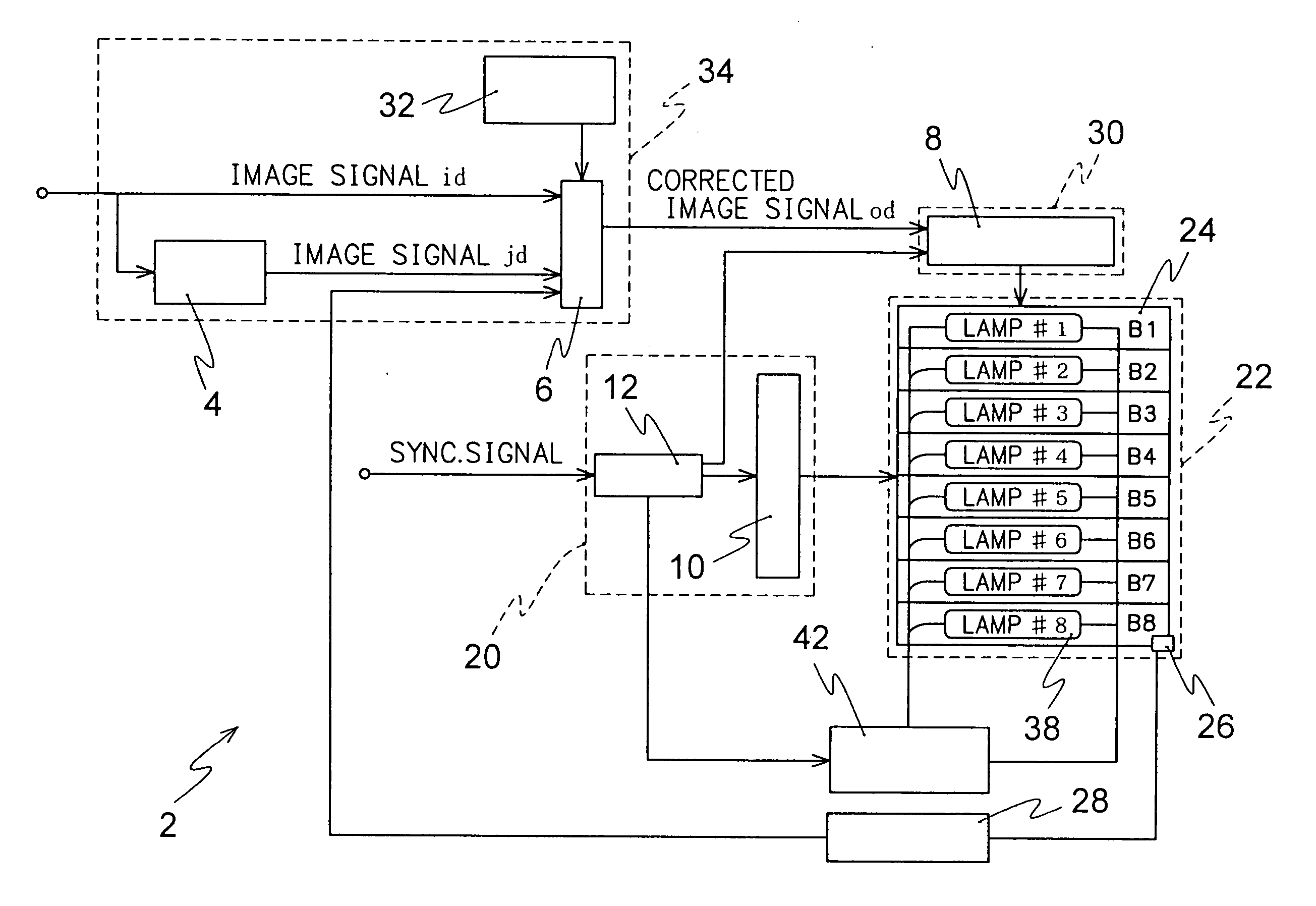
[0160]FIG. 4 is a view showing a structure of a liquid crystal display device according to Embodiment 3.

[0161] As shown in FIG. 4, the liquid crystal display device 2 according to Embodiment 3 comprises an image signal processing circuit 34, a vertical driving circuit 20, a horizontal driving circuit 30 and a display panel 22. A display are 24 is formed in a display panel 22. The display area 24 is illuminated from the rear side with a backlight. In the display area 24 of the display panel 22, the pixels are arranged in a matrix-like rows and columns configuration and a switching device such as a thin film transistor (hereinafter referred to as a TFT) is connected to each of the pixels. Incidentally, in FIG. 4, the pixel and the TFT are omitted. The vertical driving circuit 20 comprises a gate driver 10 connected to the gate electrode of the TFT via the gate wiring, and a control circuit 12 for sending a timing signal to the gate driver 10. Whole display area is scanned while drivi...


PUM


Abstract

A liquid crystal display device comprising a including signal correcting means correction for correcting a level of an original image signal to a level with which transmittance in a steady state of the pixel with the original image signal is attained within one frame period, a horizontal driving means for driver applying a voltage in correspondence with the corrected image signal to a liquid crystal material, and an illumination device for illuminating the display panel with a plurality of light emitting regions thereof, said the light emitting regions sequentially turns turning on and off in synchronization with the application of the corrected image signal, while holding a definite time delay thereto.

Description

BACKGROUND OF THE INVENTION [0001] The present invention relates to liquid crystal display devices, and more particularly to a liquid crystal display device having a drive means for applying a voltage to a liquid crystal of each of pixels, and an illumination light source. [0002] The liquid crystal display device (hereinafter referred to as a LCD) allows obtaining a highly precise display and has characteristics such as a low consumed power, a saved space for the display device or the like. It is expected that the liquid crystal display device holistically replaces a cathode ray tube (hereinafter referred to as a CRT) in various usages such as a computer monitor, a television display device or the like. However, since the LCD does not have a sufficient image quality in displaying a moving picture as compared with the CRT, improvement in the quality of the moving picture is expected. In particular, it is required that the moving picture can be displayed in a high image quality on the...

Claims


Application Information

Patent Timeline
IPC IPC(8): G02F1/13357G02F1/133G09G3/20G09G3/34G09G3/36H04N5/66
CPCG09G3/2011G09G3/342G09G3/3648G09G2310/0224G09G2310/024G09G2310/061G09G2340/16G09G2320/0252G09G2320/0261G09G2320/0285G09G2320/041G09G2320/0633G09G2320/064G09G2310/08A63C19/005A63J1/02A63J5/02
Inventor ODA, KYOICHIROYUUKI, AKIMASATAHATA, SHINTOBITA, TOSHIOMIYAKE, SHIROKOBAYASHI, KAZUHIROMURAYAMA, KEIICHI
Owner MITSUBISHI ELECTRIC CORP
Why Eureka
Try Eureka